Solidworks is considered a unique user -friendly program. And you have to admit, that despite many defects, service friendliness is at a high level. In folding, after clicking the part in the graphics window, a temporary menu develops, from which you can perform many operations. Poziom złożenia umożliwia identyfikację układu odniesienia, Determining and editing bonds. Poziom części daje dostęp...
Author: Paul (Paul Kęska)
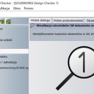
Identifying the numbers of elements in LM, which have no links
About that, that after putting the list of BOM materials you can check, Everyone knows which components do not have links. The problem arises, When the letters are long and looking for a symbol of a link in cells, it can be time consuming and you can overlook something. That's why I will show the way, in which you do not have to enlarge the table and look manually. I use for this purpose ...
Preview of the list of cut elements without creating a drawing
Welded constructions are a very useful tool. This module often speak about this, that it is such a simplified form of assembly, which of course is not the end of the truth. But many tools work similarly, Hence my term. It certainly is not possible to insert a list of materials as in the assembly. But are you sure? Of course, that you can insert a list of materials, before...
Reverse the tangible end point and square
W SOLIDWORKS 2025 SP1 (and certainly in SP2.0) There are two interesting sketch options. You will like one in particular – I missed her very much. Well, by drawing a Rectangle with the SHIFT key pressed, you will get a Square! see also: Three ways to draw a square. You know them? The second less important change is the ability to reverse the arc tangency. Takes place....
SOLIDWORKS 3D models
A long time ago I wrote about the settings for printing in the File tab > Print3d. Yes, in SolidWorks there is a possibility, Just like in an ordinary printer, Printing parameters settings and supports check, thin walls, layers etc.. Unfortunately, not all printers are on the list, ale można użyć domyślnych ustawień w celu zorientowania się na temat potencjalnych problemów z wydrukiem....
Better and faster viewing of projects in PDM
imagine, that you receive SolidWorks for further processing. You work in the PDM environment, and the files are already in the storage room. You want to quickly assess the degree of complexity – What are you doing? In SOLIDWORKS PDM, on the Preview tab, you can see a 3D image of the assembly. Pressing the E key will create an automatic explosion – So you can quickly check the content of the assembly!
Repair a break not always a better choice
By opening files imported from systems other than Solidworks, errors may appear. The amount and type of errors depends on a number of factors. On the example of the model, I will show you a break, how the machine works and what effect you get by manually repairing the problem. Fix Gap can be found in the Import Diagnostics window after right-clicking on Gap. The command was fixed by the error, but the quality of the resulting....
Create a sketch from selected VS elements. Convert the elements
The command called Create a sketch from selected elements creates a sketch from selected segments. Especially in my opinion, this is useful during 2D to 3D conversion. Create a sketch from selected elements when converting 2D to 3D But today I will show the difference between this command and the Convert elements operation. When converting, you must first be in the active sketch,...
Automatic repair of references in the formation
Situation, in which, after making changes to the models, the style displays errors, I think it is quite common. Similarly in folding. As with fillets, there is a tool to fix outdated references. Errors in rounding – how to quickly update outdated references To repair a pattern in an assembly, you can add the appropriate command via Customize or choose from....
Saving parts and assemblies with FEA parameters
In SolidWorks Simulation, it is possible to add a single parameter to the library (e.g. predefined force). You can also do it massively. To create an operation from the analysis library, first you need to create a study, where the analysis operations to be included in the analysis library will be defined. You can create analysis libraries from part documents (including multi-object) and assemblies. Rozszerzeniem plików Biblioteki analiz...


