A long time ago I wrote about the settings for printing in the File tab > Print3d. Yes, in SolidWorks there is a possibility, Just like in an ordinary printer, Printing parameters settings and supports check, thin walls, layers etc.. Unfortunately, not all printers are on the list, ale można użyć domyślnych ustawień w celu zorientowania się na temat potencjalnych problemów z wydrukiem....
Author: Paul (Paul Kęska)
Better and faster viewing of projects in PDM
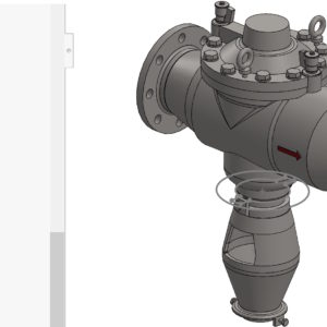
imagine, that you receive SolidWorks for further processing. You work in the PDM environment, and the files are already in the storage room. You want to quickly assess the degree of complexity – What are you doing? In SOLIDWORKS PDM, on the Preview tab, you can see a 3D image of the assembly. Pressing the E key will create an automatic explosion – So you can quickly check the content of the assembly!
Repair a break not always a better choice
By opening files imported from systems other than Solidworks, errors may appear. The amount and type of errors depends on a number of factors. On the example of the model, I will show you a break, how the machine works and what effect you get by manually repairing the problem. Fix Gap can be found in the Import Diagnostics window after right-clicking on Gap. The command was fixed by the error, but the quality of the resulting....
Create a sketch from selected VS elements. Convert the elements
The command called Create a sketch from selected elements creates a sketch from selected segments. Especially in my opinion, this is useful during 2D to 3D conversion. Create a sketch from selected elements when converting 2D to 3D But today I will show the difference between this command and the Convert elements operation. When converting, you must first be in the active sketch,...
Automatic repair of references in the formation
Situation, in which, after making changes to the models, the style displays errors, I think it is quite common. Similarly in folding. As with fillets, there is a tool to fix outdated references. Errors in rounding – how to quickly update outdated references To repair a pattern in an assembly, you can add the appropriate command via Customize or choose from....
Saving parts and assemblies with FEA parameters
In SolidWorks Simulation, it is possible to add a single parameter to the library (e.g. predefined force). You can also do it massively. To create an operation from the analysis library, first you need to create a study, where the analysis operations to be included in the analysis library will be defined. You can create analysis libraries from part documents (including multi-object) and assemblies. File extension of Analysis Libraries...
Create a current view as, that is, a change of orientation
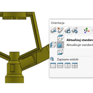
The orientation of the view can be changed in several ways. One of them is to press the spaces, and then update the standard views. W taki sposób możesz w dowolnej chwili zamienić widok np. przedni widokiem np. od góry (or any other). Zaznaczę wyraźnie, iż to jest wyłącznie zmiana orientacji – nie ma nic wspólnego z fizycznym obrotem modelu w...
Linking the configuration name with a drawing view
If in the figure you present a lot of configurations of the same part, it may be useful to describe them. It's not about adding a description manual, But linking the configuration name with the view. To do this correctly, add a related note to a given view. Related means, that you have to put it in the view area (pink frame) or from the so -called. leading line. Then...
How to find a part of the deposit received all the degrees of freedom?
As is widely known, Unexput sketch contains the designation before the name (-). you can tell, that it is similar in the folds – parts, who do not have fully limited ties have an identical designation (-). How can you track such components? 1. Visual assessment, primitive and not very effective in the case of more folding. Unfortunately, entering in the filter field (-)...
Operation from the library for bending metallurgical profiles
As you know, process automation allows you to significantly shorten the working time. If you bend the profiles sporadically and you don't have specialized software – that's okay. With the help of operations from the library, you can do such a tool yourself. How does my operation work? I created four configurations, in which the number means the amount of bending. Operations are based on ...


