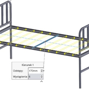
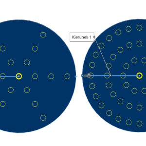
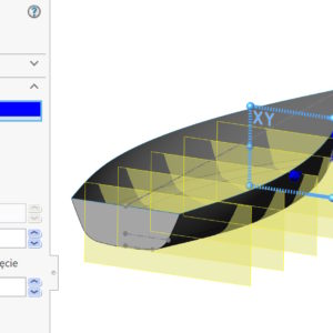
Wykonując szyk czy to operacji czy obiektu, czasem istnieje potrzeba wykonać go w dwóch kierunkach. Oczywiście możesz niezależnie zdefiniować parametry dla kierunku 1 oraz oddzielnie dla kierunku 2. Jeżeli rozstaw i ilość powtórzeń są identyczne dla obu kierunków, to dlaczego nie zastosować rozwiązania znanego z Szyku kołowego? W takim przypadku dla kierunku 2 możesz włączyć...
Category: <span>Tips n Tricks</span>
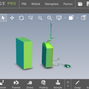
Use software OpenGL in eDrawings
Do you know, that it is also possible to enable OpenGL programmatically in the eDrawings application. What kind of option is this? Software OpenGL disables graphics card hardware acceleration, enabling software-only graphics rendering. This option is automatically enabled, if the graphics card does not support hardware acceleration or does not have the appropriate drivers (for the current resolution settings, colors, refresh rate etc.)....
The section view: Planarne vs. Strefowe
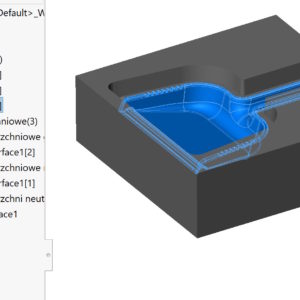
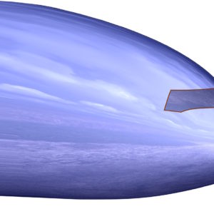
The section view in SOLIDWORKS allows you to graphically cut a 3D model. Word “graphic” By default in SOLIDWORKS in, that the cut is not geometric, therefore, you cannot insert a sketch on a section face. In the location method you can choose between options: Planar and Zone. The latter is less known, even though it appeared already good 10 years ago, no less since the beginning of existence....
Delete/Keep Objects – how to do it faster
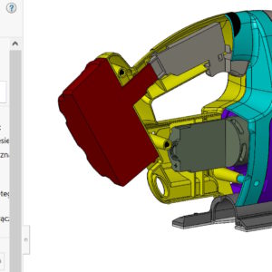
By-products may be created during 3D modeling – I mean auxiliary surfaces or unnecessary solids. I think, that everyone should clean up after themselves after finishing work, i.e. remove all unnecessary objects. We do this using the Delete/Keep Objects operation. Of course we choose this option, where there are fewer objects to select. However, I wanted to draw attention, that...
Cylindrical border box
The border box with a range of uses has gently evolved. I have already written about the various options and applications of this tool. Bounding box in parts, , assembly and welded structure The standard frame has a cuboid shape and can be adjusted optimally or to the indicated reference. To, what I wanted to present is the possibility of generating a cylinder-shaped frame. Of course in....
Different ways to finish a 3D model smoothly
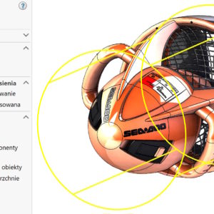
In modeling, we are often faced with choosing a specific operation. But to be able to choose optimally in a given situation – you need to know these operations. I'll show you today, how to finish a rounded shape smoothly. It may be the end of a construction hook, the tip of a pen or the nose of an airplane. 1. Dome. I'll start with the surgery, which only works on solids, and which allows....
Target spacing vs. Instances per loop
The fill pattern is a very functional pattern operation. Fill pattern with circular arrangement from the corner Performance comparison in sketch and feature patterns You can use it to duplicate your own shapes or use (in the case of cutouts) of four built-in. In the case of a Circular formation, you can choose from two options: 1. Target spacing – define the angular spacing on individual....
Configuring dimension accuracy and tolerances in Excel
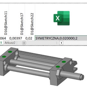
You can control tolerances in the design table as follows: In a part, you can control dimension tolerances in sketches and features. In assemblies you can control the so-called dimension tolerances. assembly operation. This includes bindings (angular or distance), assembly feature cuts and holes, and component patterns. You cannot control the dimension tolerances of a component contained in an assembly. Column header in a table...
Bidirectional extrude from approved sketch
Do you know, that by clicking on the approved sketch you can pull it out using the arrow. Of course, a better technique is to use the sketch directly (without committing) in basic operations. However, you can confirm the sketch and select the extrusion from the graphics window. However, the prerequisite is that Instant3D is enabled in the Operations tab. Instant2D vs Instant3D Comparison So by extruding the sketch in a specific direction,...
Multiple planes – substitute solution
You can insert multiple planes at the same time, both linearly and angularly arranged. There are many applications, one of them may be preparation for framing sketches. But… thus inserting planes, will be created in the tree as each independent. So after approval, it is not possible to edit the spacing or quantity “in formation”. Meet my solution. Instead of the starting plane....

