Do you know, that… ?
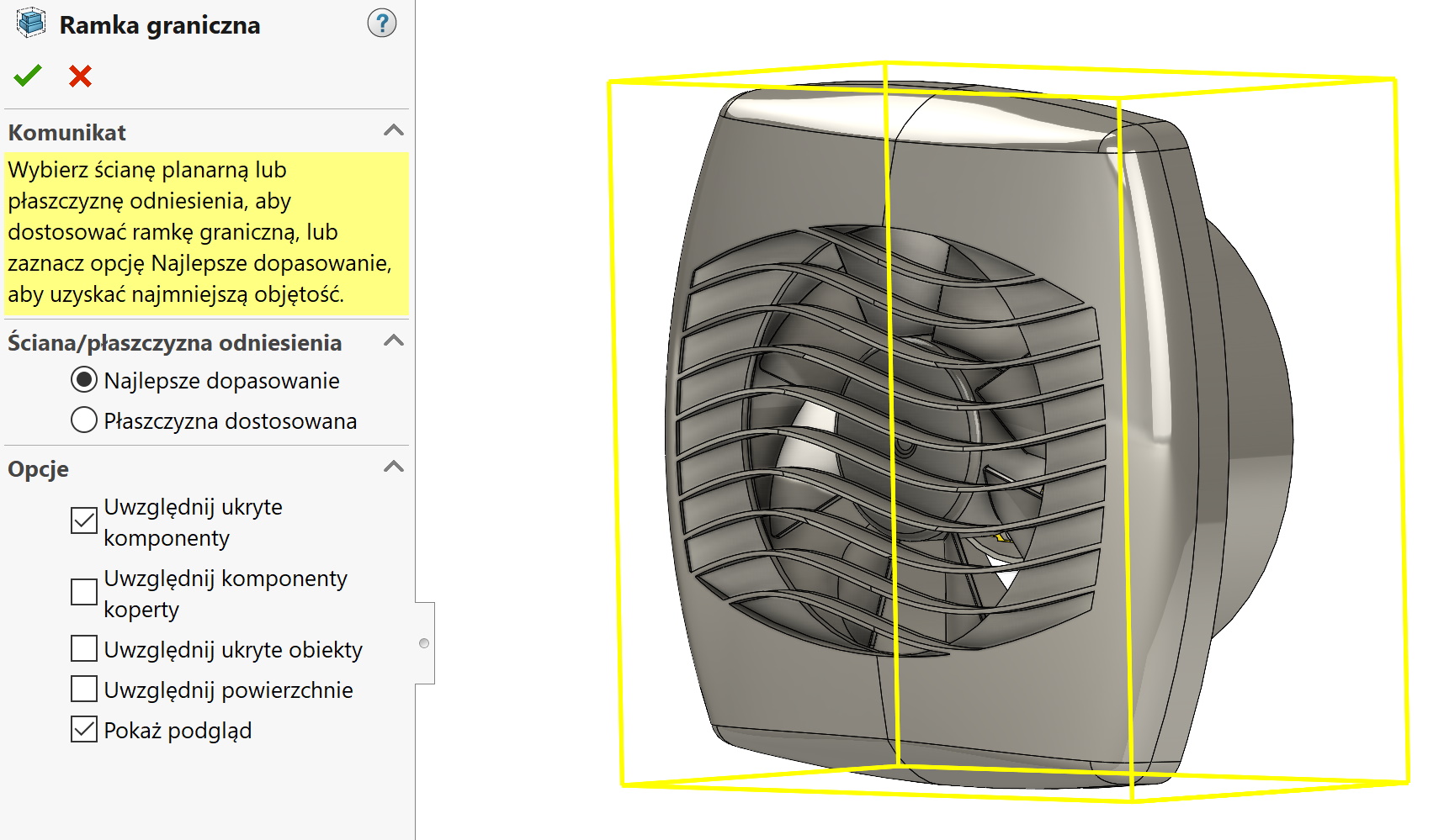
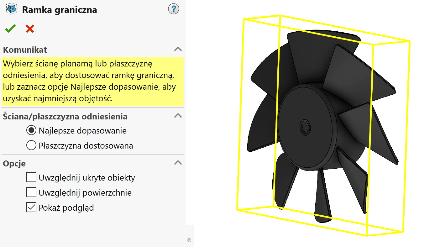
Bounding box available on the card Reference geometry (or in the Insert menu > Reference geometry) lets you type a part, a composite or a cuboid object with minimum size.
This tool is therefore particularly useful in designing packaging and quickly calculating dimensions.
In the part and assembly, the frame is inserted identically on the card Reference geometry.
You will find the frame in the operations tree, however, at this point you can only see the dimensions in the window when held down with the cursor.
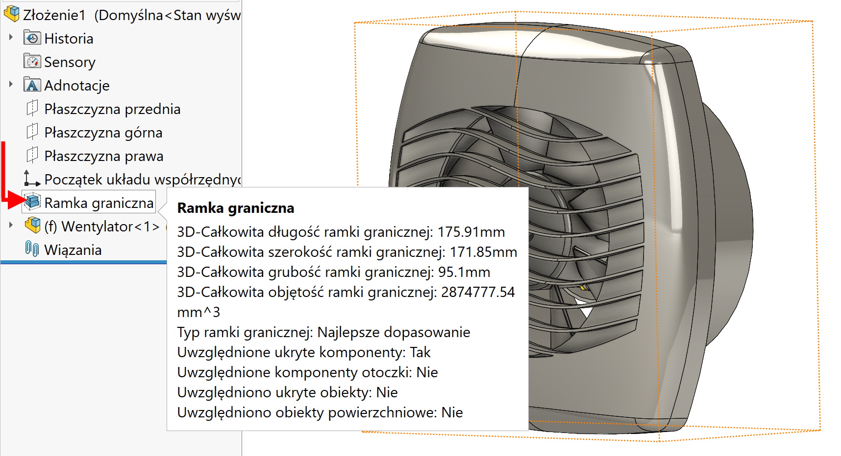
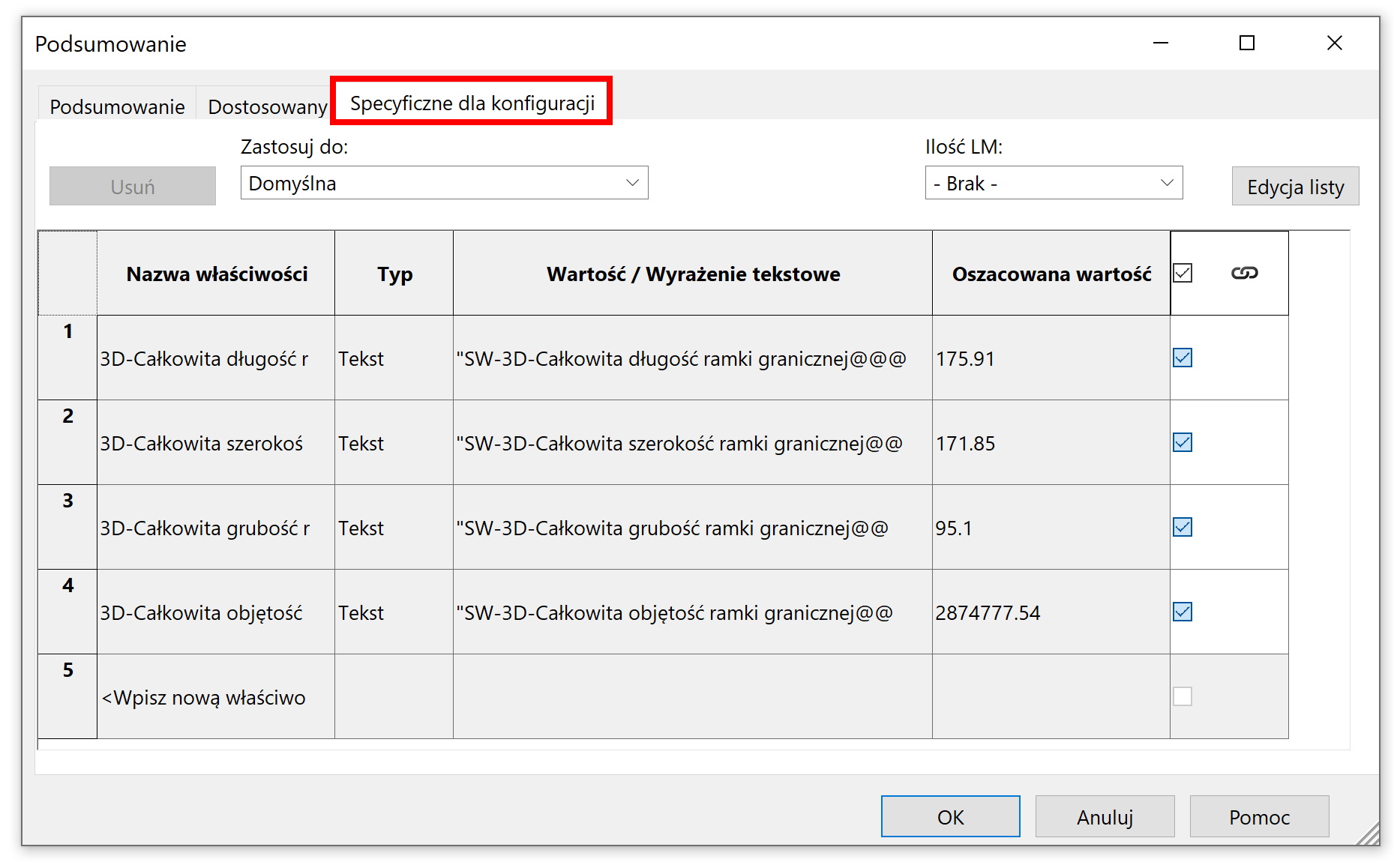
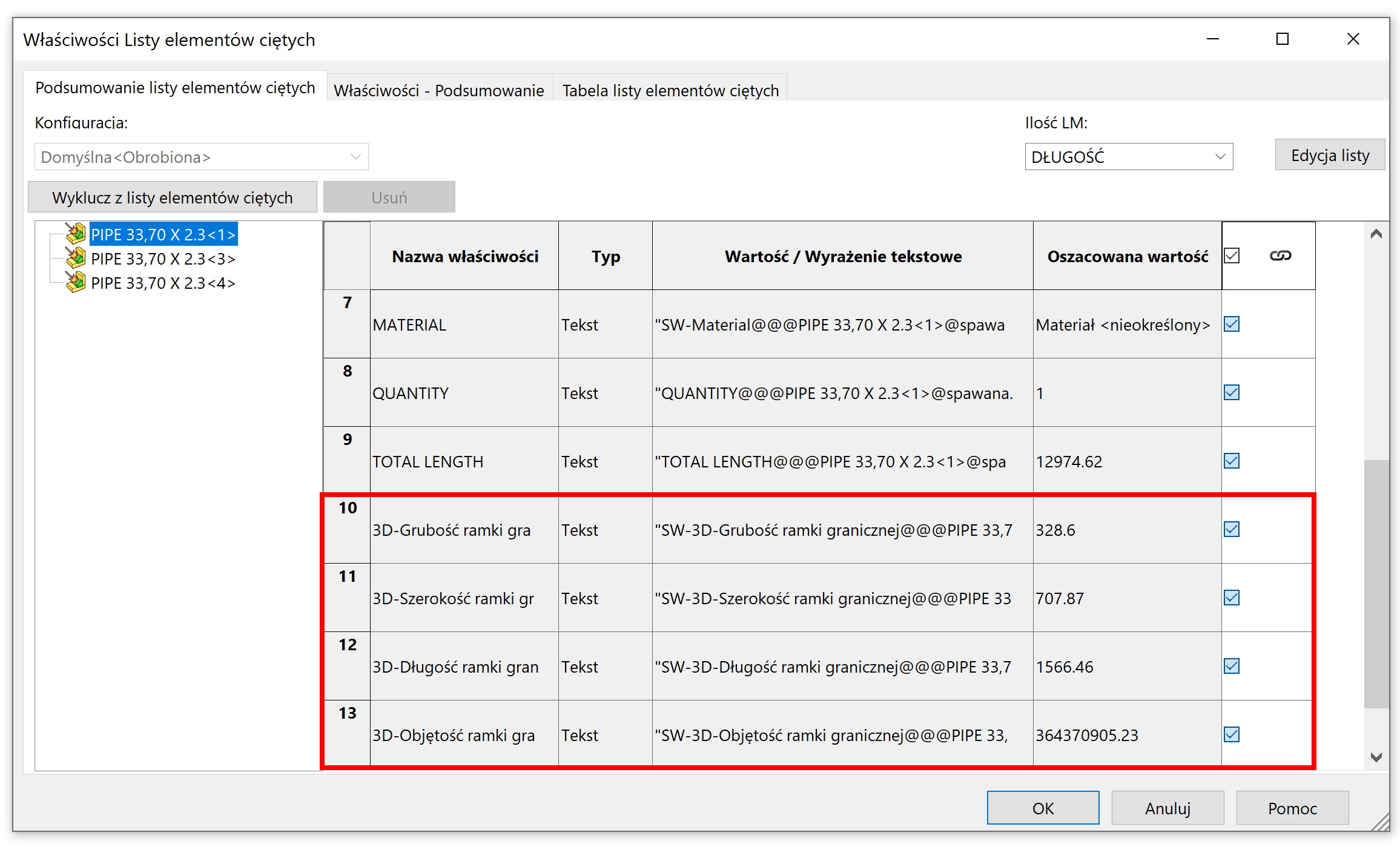
If you want to get the values into the BOM table or title block, you should go to properties > Configuration specific.
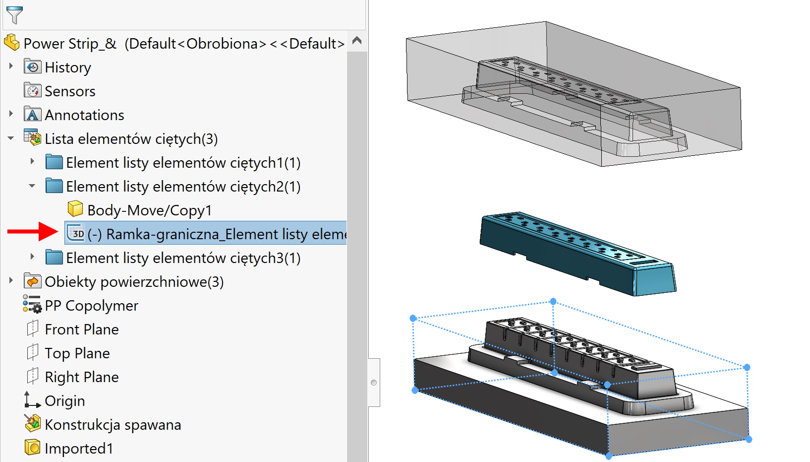
In the case of welded structures, a frame is inserted after right-clicking on a selected position in Cut leaves.
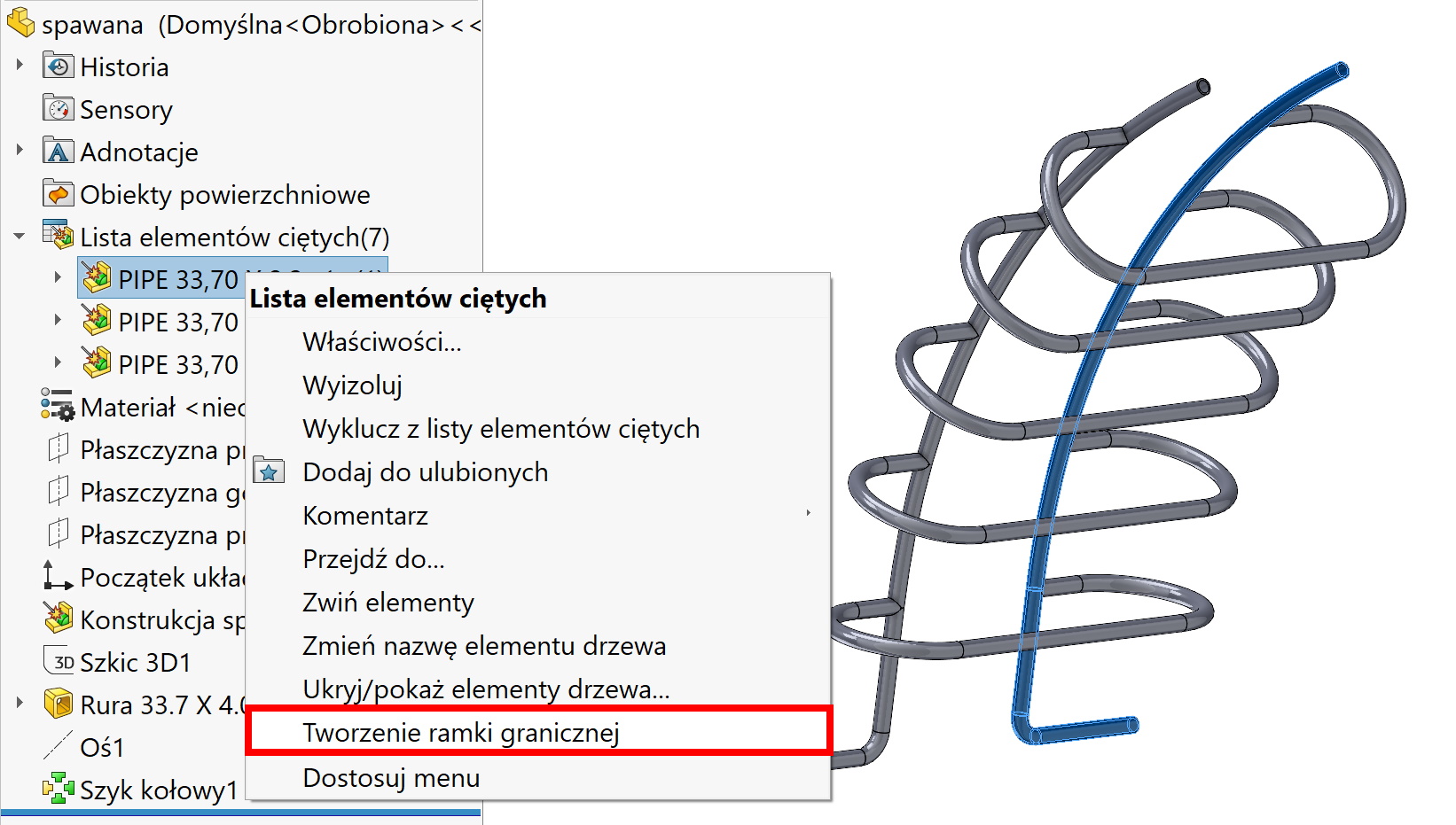
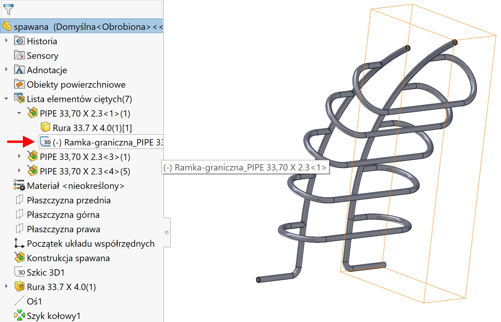
You can find the inserted frame after expanding the cut list folder.
The numeric values, on the other hand, are available in the properties of the object as four additional entries.
attention! If you want to insert a bounding box in any multibody part, the program will take into account the entire part. Therefore, you must enable the command Welded construction and update the list manually. Then proceed as with a typical construction – that is on object level in the cut list.
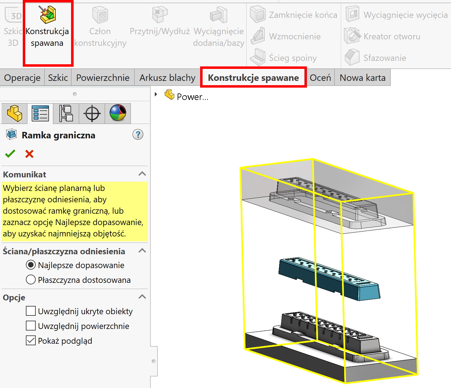
The frame will be generated in a folder Cut list item.