Do you know, that… ?
There are three types of split lines:
- Silhouette
- Projection
- Intersection
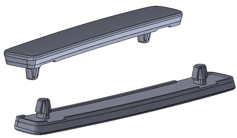
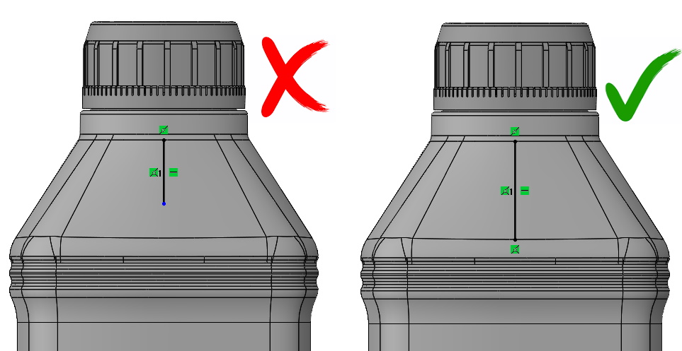
Each of these types has a different use. Generally Split line is used to divide the walls, that is, creates edges. The edge created must result in at least two walls. Could not create split, which does not create a wall. In other words, drawing a sketch line on the wall, it must extend beyond the outline or join with the edges, otherwise there is no division.
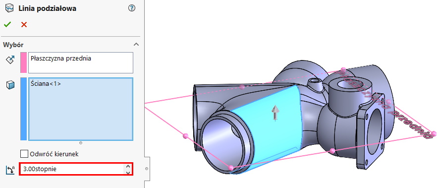
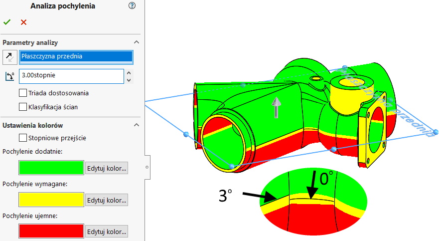
Silhouette allows “pass” selected plane by model, which creates an edge at the transition from positive to negative angle or vice versa.
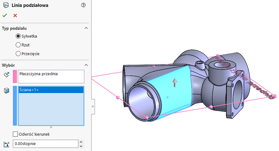
You can control the angle, so that the split is created according to the required skew.
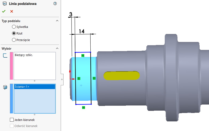
Type dividing line Projection is used to create the edge by sketching the selected wall (in both directions or in the selected one). remember, that the projection occurs perpendicular to the sketch plane, so you can say, that the operation works within 180 degrees (e.g. when projecting onto a side wall of a cylinder).
This operation has many uses. It is commonly used during Simulation calculations. If not for the dividing line, it would not be possible to simulate the support of a long shaft, or applying force to a separate wall.
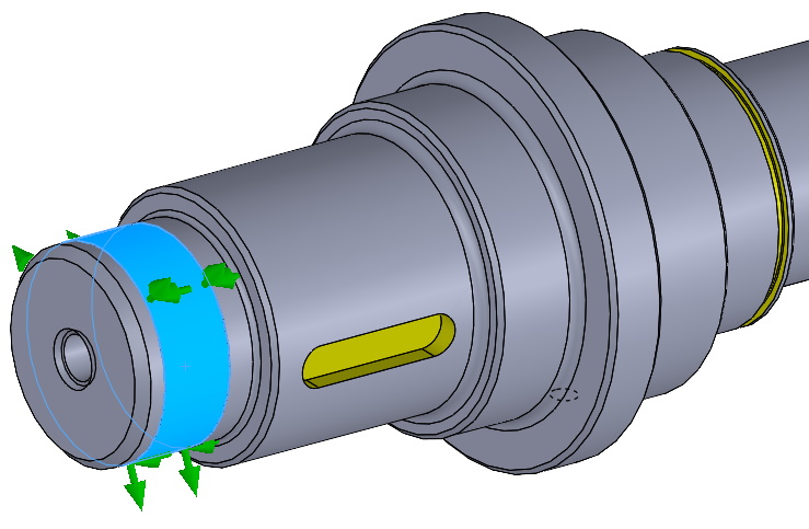
The operations are used in visualizations, to create walls, to which we assign a specific appearance.
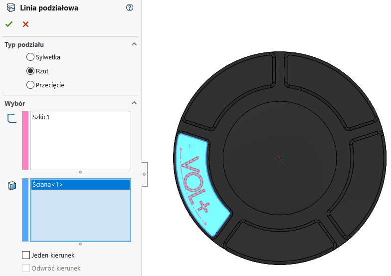
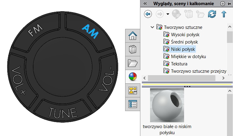
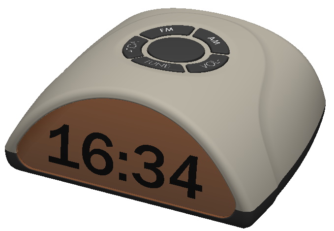
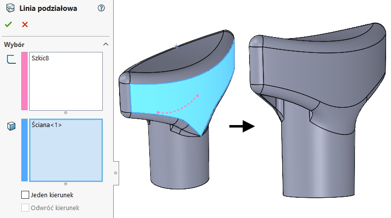
The projection can also be used to separate walls, which are later smoothed out. Often this type of split is also used to repair imported files.
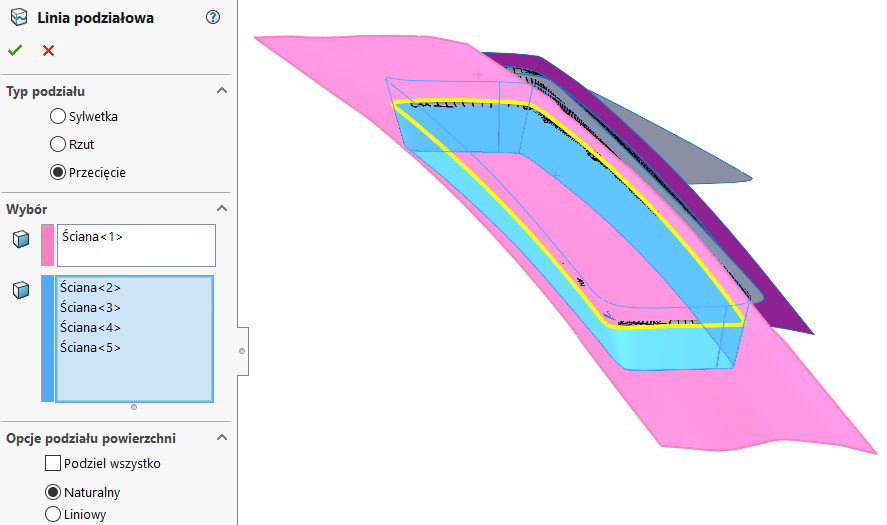
The last type of split line is Intersection, which creates edges at the intersection of two or more surfaces / walls, or at the intersection of a plane with a surface / wall.
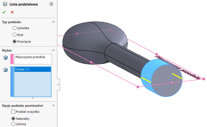
The intersection can be used in the conversion of a scan to a surface, where, having many surfaces, edges are formed at the intersection.
