Do you know, that… ?
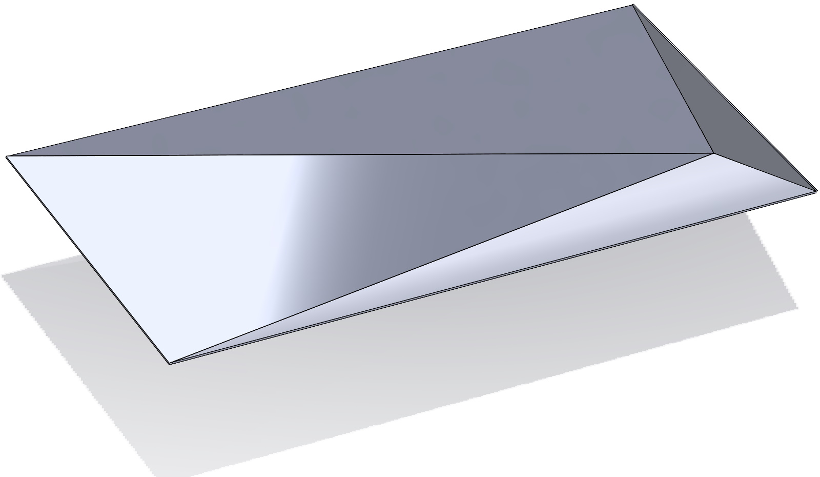
There is a sheet metal gutter to be made, in which the triangular end cap is a separate body. What's the best way? I will show you three solutions.
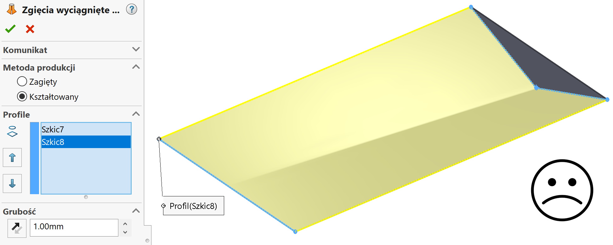
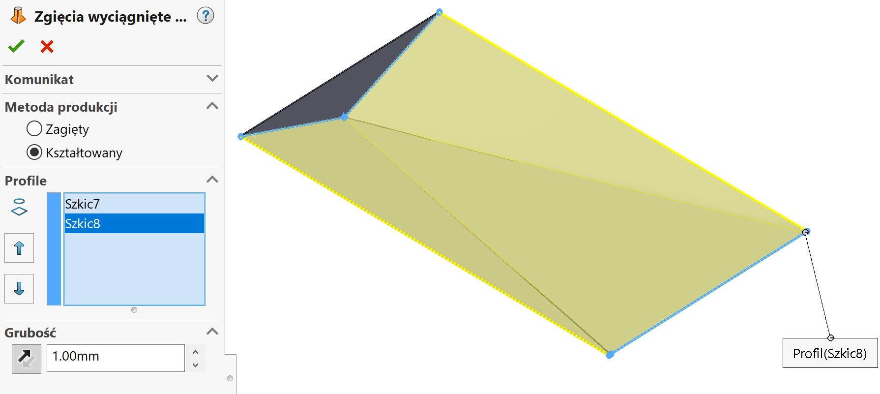
- Loft method.
Requires that you draw lines in two separate sketches. On the one hand, one line is enough, on the opposite side, two lines at an angle, additionally rounded. Unfortunately, this solution will not achieve the desired effect.
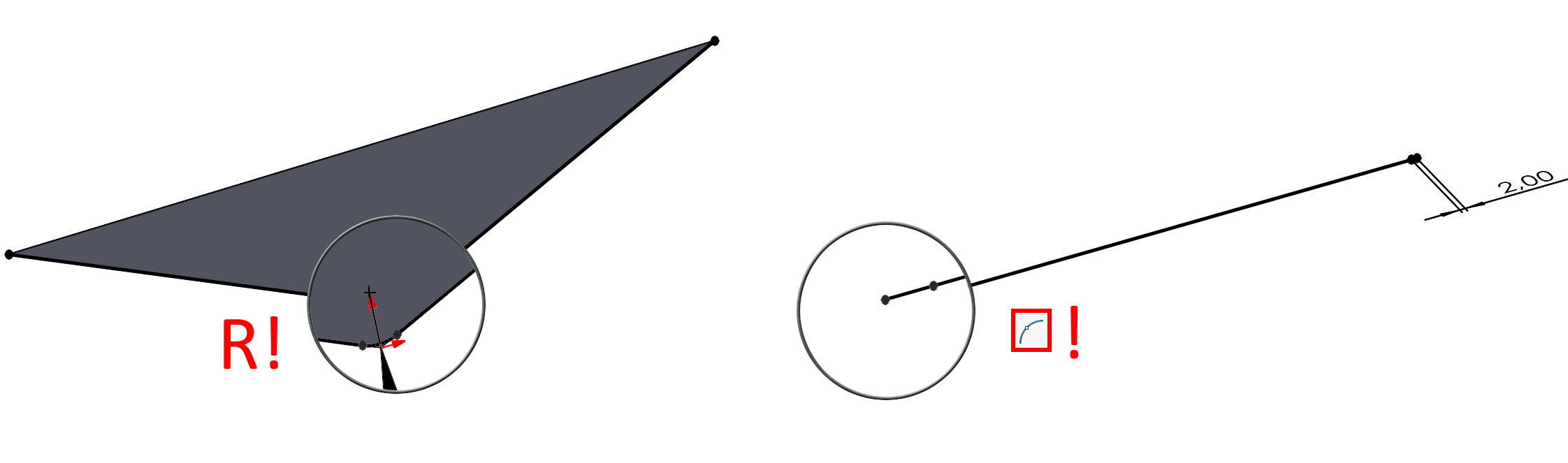
So that the lofted bend turns out to be correct, insert two additional sketch split points. In this way, the program will connect successive points of the sketch with virtual connectors and you will get the effect of flattening. If you have doubts about the action, temporarily use the surface extrude, and observe the fasteners (you can select under the right button Show all links).
Also remember to add a radius on the other side, because you cannot use a sketch with a sharp point.
Only now does this operation make sense. No less using options Shaped bend lines cannot be displayed. Second option Folded with such parameters it will not work.
2.Method two is the base flange plus the edge flange.
In the first step, I insert a plane and draw a triangle on it. You will use this sketch to create the base flange.
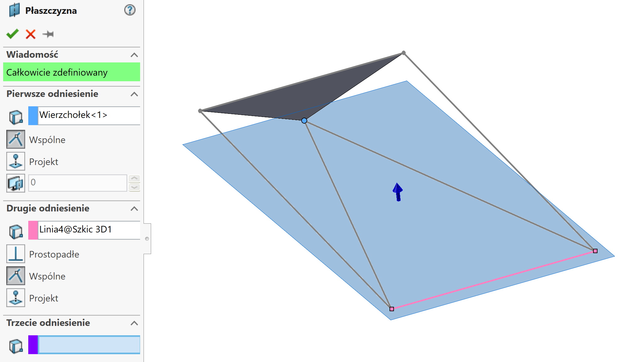
Then I fold the edge away by selecting Parallel to the wall (referring to the triangle drawn earlier). The flange length defines the vertex of the triangle.
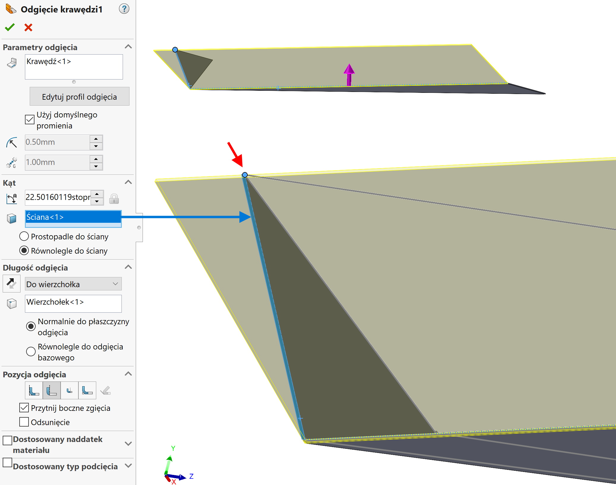
I repeat the procedure on the other side, before that I create a small undercut in the corner. If the plate tapers to a sharp point, it is impossible to deflect it with a mirror, because the bends overlap.
The last stage is cutting off the allowances. I use a rectangle and cut through everything with option Flip side to cut and cut perpendicular.
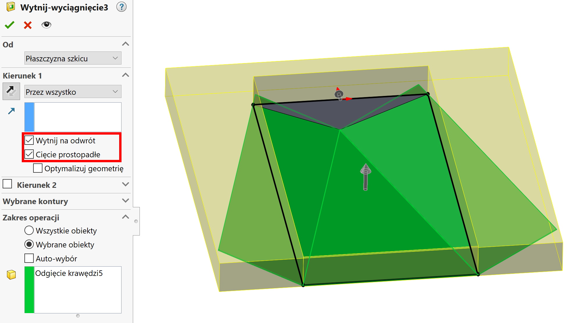
Of course, the sheet metal and the sheet made using the first method decomposes.
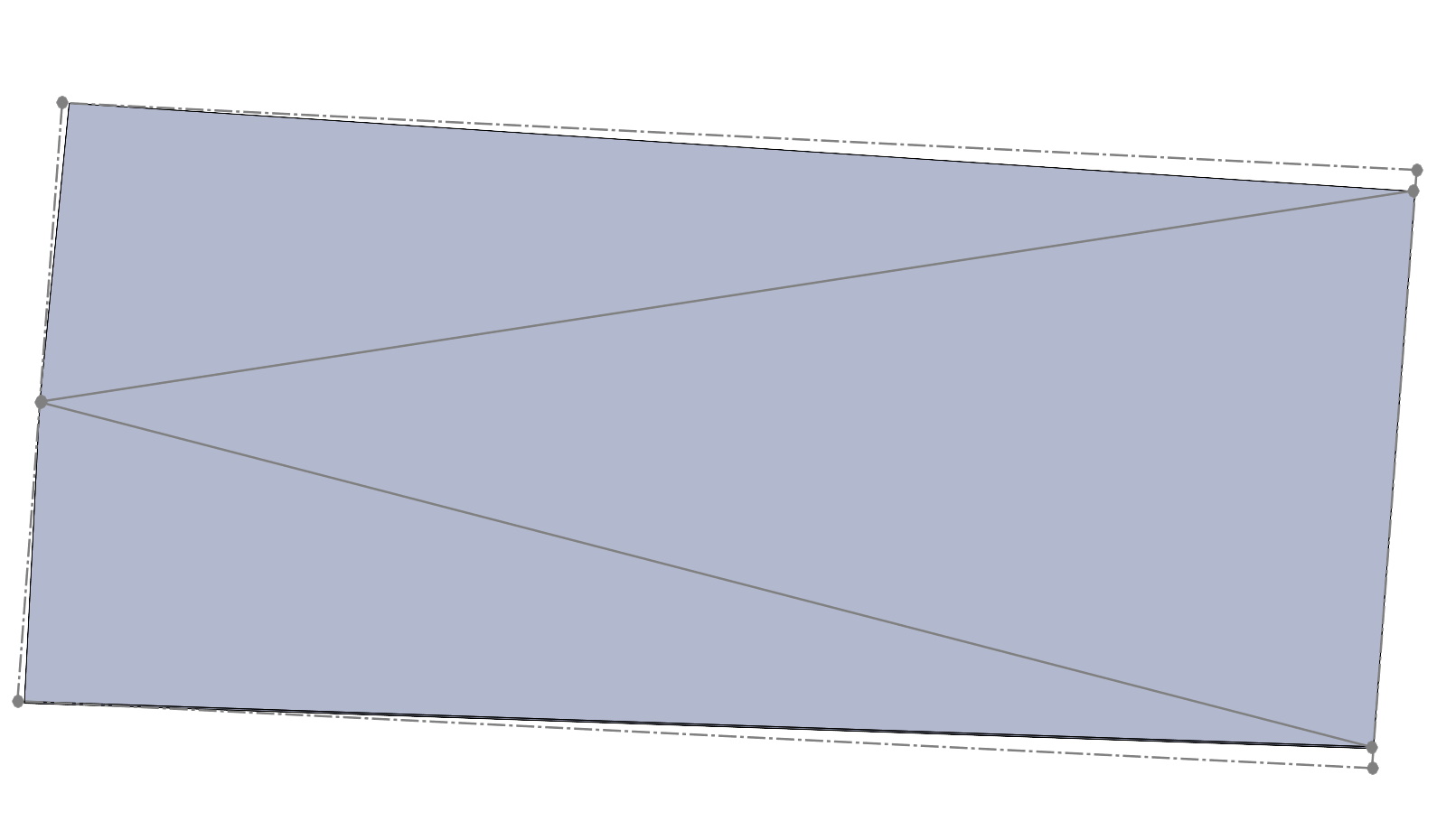
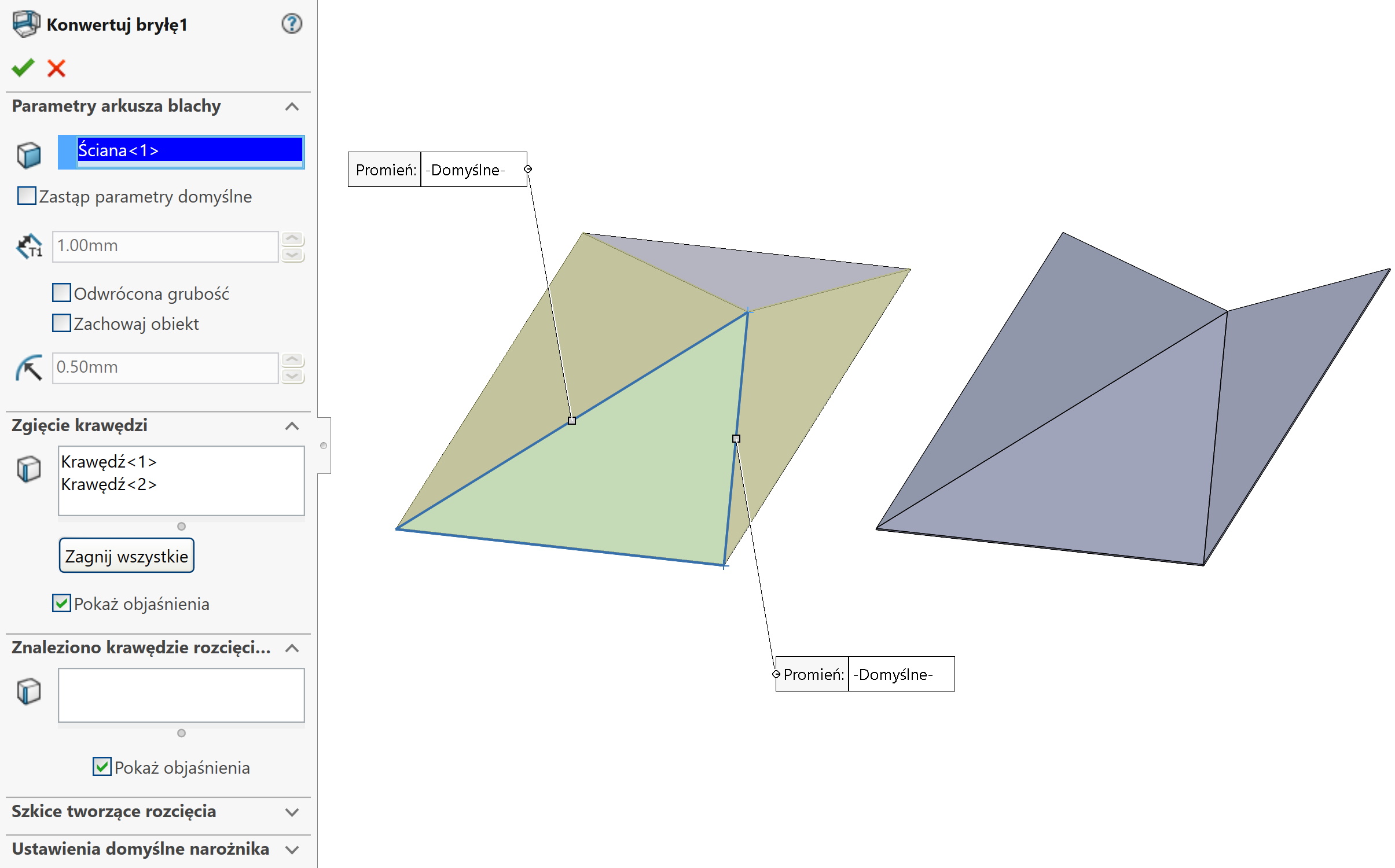
3. Last way. Since we have a flat expansion, it could be a reverse process. This is what you do by converting sheet metal drawings into 3D models – you can read it in mine the textbook>>>.
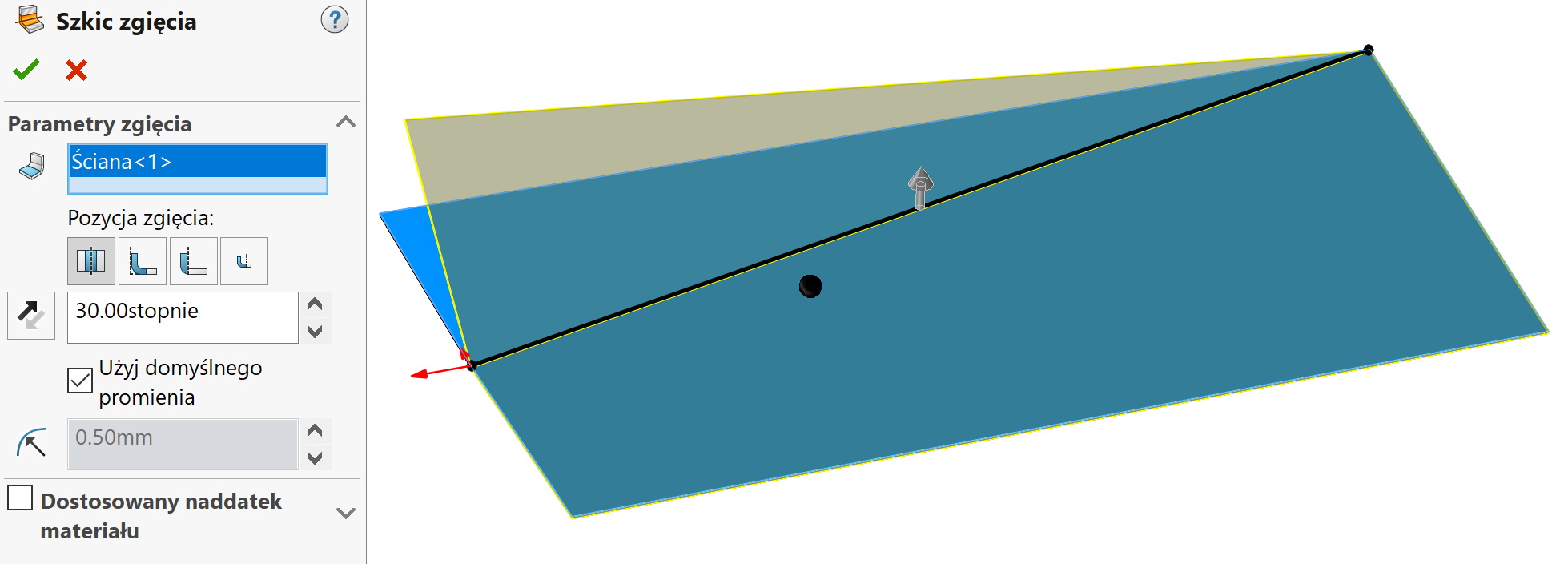
By reversing the process, I mean creating two bends on the flat sheet model. You need to draw a line that corresponds to the bend line, then you have to choose Sketch of the bend. Unfortunately, the angle has to be calculated (or measure) in an existing triangular model. And the operation must be repeated, because you cannot draw two lines in one step, which may intersect.
Of course, these aren't the only three methods, there is e.g.. the possibility of making such a sheet by converting from a 3D model. And as long as the conversion itself is simple, because you need to select the two edges to be bent, this model preparation may be complicated for some. I made a model with a surface by joining the lines of a 3D sketch.