Do you know, that… ?
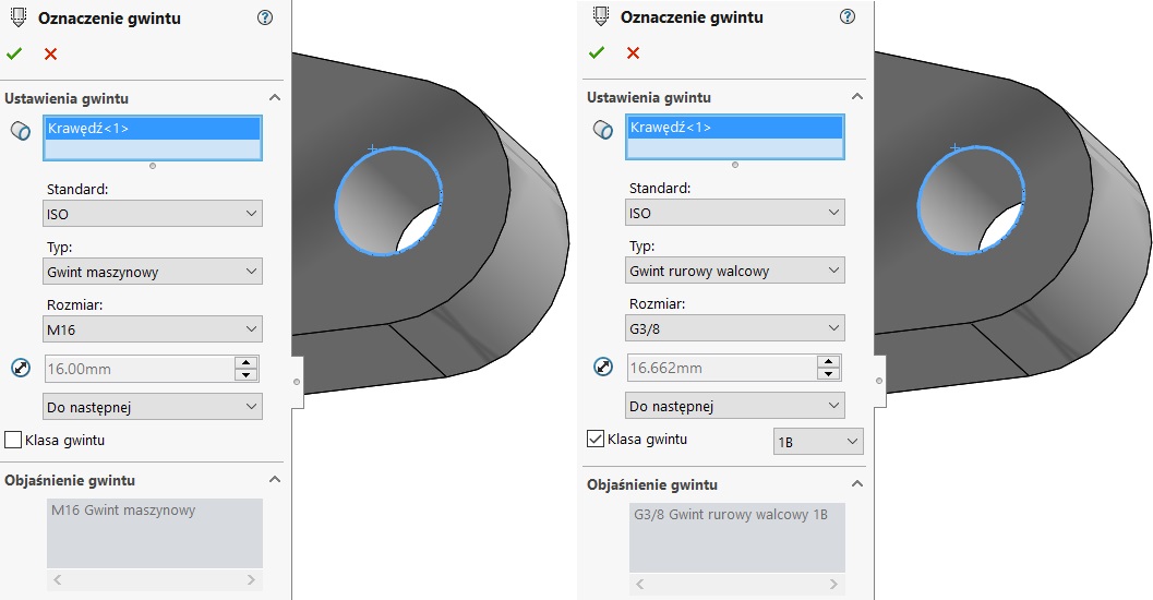
You can get a threaded hole in one of two ways sOlidwOrks. The first is the use of naturally hole wizard, where one of the types is a threaded opening (annotation thread). The second option is to make the opening any method and can manually insert Cosmetic Threads.
And what are the possibilities of dimensioning in the drawing thread?
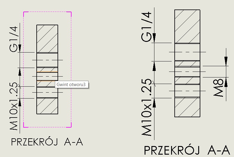
1. Dimensioning intelligent dimension.
In the case of the thread with the term (not physically cut) you can use the normal working by checking the outer diameter (thread in the hole) which is to insert a thin line dimension. It should identify the type of thread insert and label eg. M8. In older versions do not always work properly this way, often display instead of the program “M” symbol “∅”.
2. Insert explanation.
This method is based on the information stored in the sign of the thread in the standard. Choosing not standard, you can manually enter the text, and thread parameters.
In drawing such explanation you can insert after right-clicking on a line / arc thread > Insert explanation.
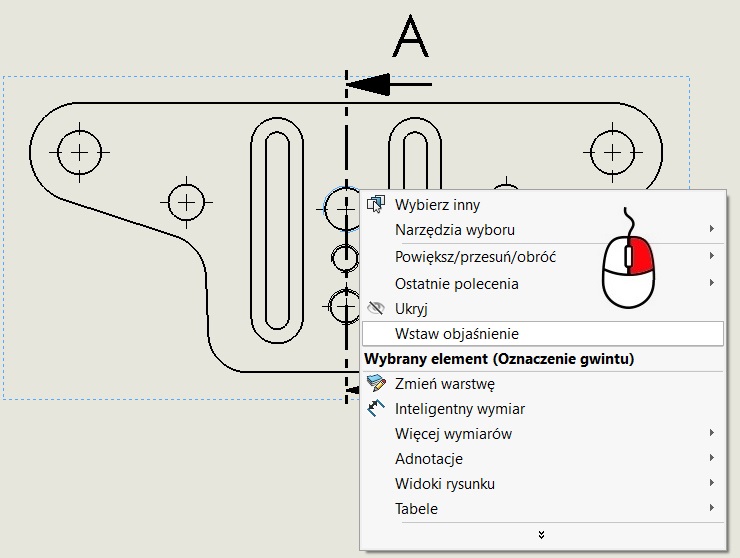
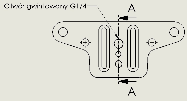
After you insert the annotation is as follows:
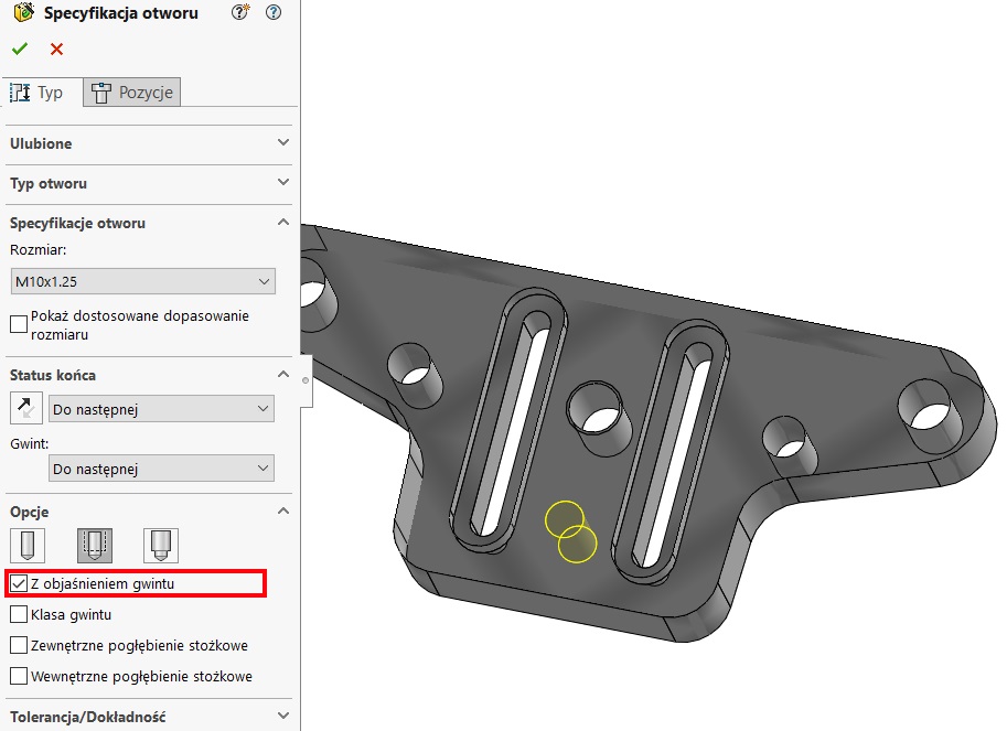
3. Explanation hole.
The last way is to use the general operation Explanation hole, dedicated to the different types of holes – Also this is not coming from the wizard.
I assume, however,, that the bore holes created creator. In the options, you must select In the explanation of the thread, because the clearing of the field results in an empty annotation in a drawing.
Being in the drawing window, select the icon Insert explanation, which is located m.in. on the card annotation. 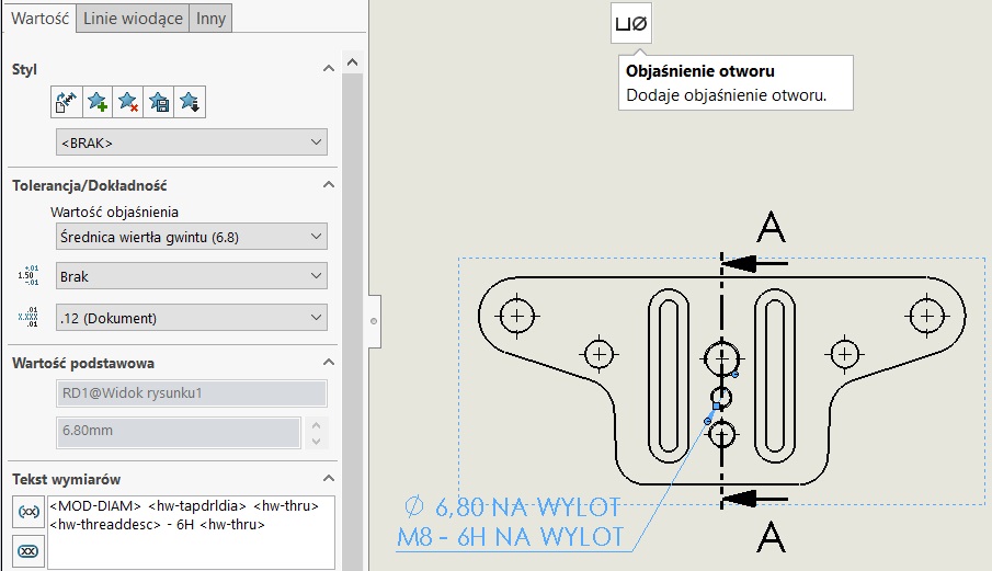
If you want to modify the scope of the information displayed, You can do it locally in properties, removing the corresponding string in the window text dimensions.
To permanently modify these values, language directory, locate the file named calloutformat.txt and a suitable type of opening required to set variables. This file is structured xml, easily confused – so it is good to create a copy of the earlier (one copy is automatically created – calloutformat_2.txt).
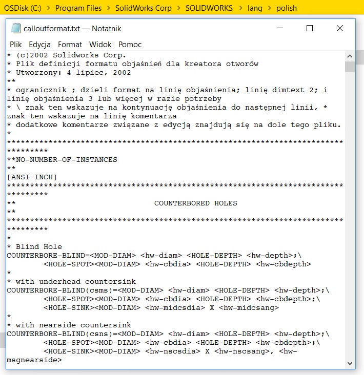
The correct variables for the wizard holes are as follows:
* Depth of counterbore
* The diameter of the counterbore
* The angle of the cone drill
* Conical drilling depth
* The diameter of the cone drill
* Countersink angle
* The diameter of the countersink
* Depth
* Description
* Diameter
* angle drill
* Status end
* Angle of internal countersink
* The internal diameter of the countersink
* fastener size
* type connector
* interval head
* hole depth
* Hole diameter
* The central angle countersink
* The diameter of the central countersink
* inner diameter
* outer diameter
* External angle countersink
* Diameter of the outer countersink
* Slot Length
* Standard
* Depth drill Thread
* Drill diameter of thread
* thread angle
* class thread (1B, 2B or 3B, It applies only to otowrów ANSI Inches)
* thread depth
* Thread Description
* thread diameter
* series thread
* thread size
* hole depth
* Hole diameter ,
* The diameter of the threaded hole
* The depth of the threaded hole
* Type
Leave a Reply