Do you know, that… ?
The joints in welded structures can insert both in the 3D model and drawings.
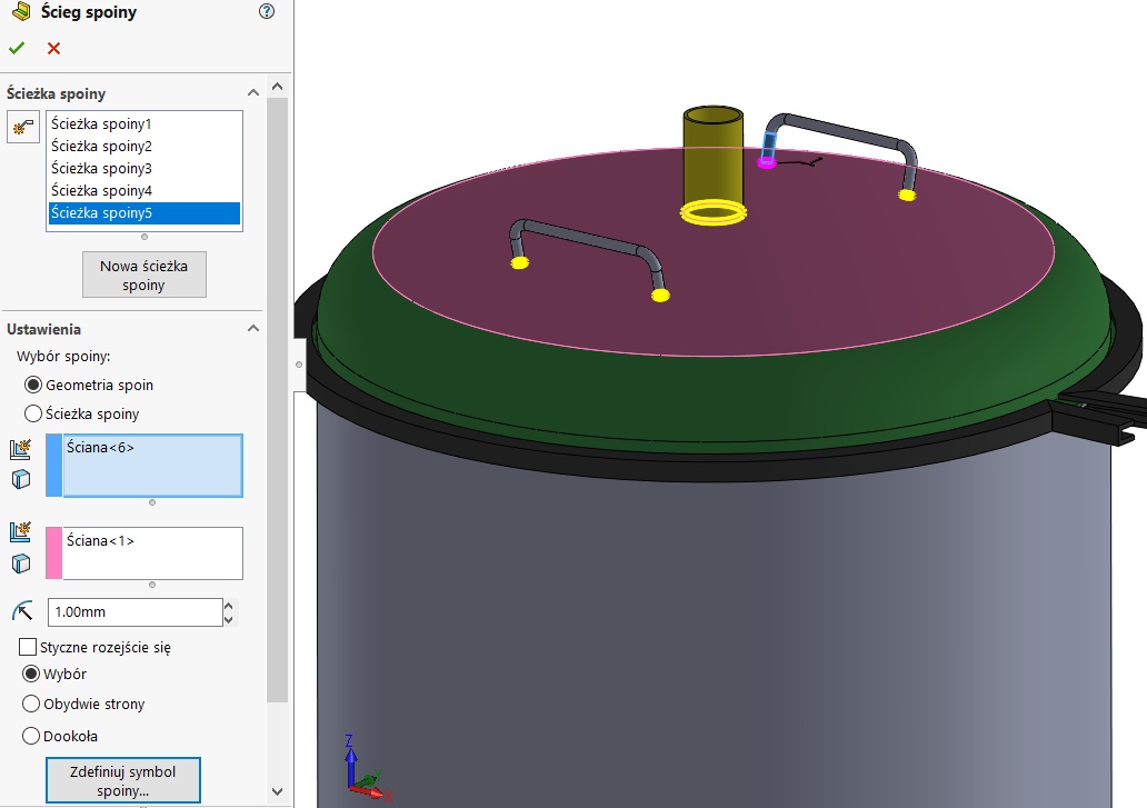
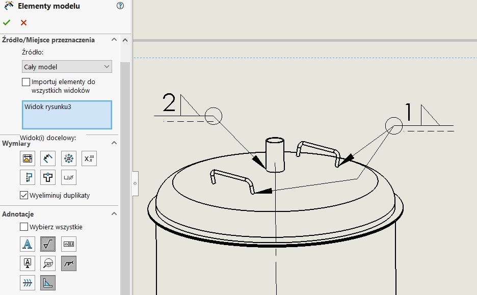
If you put in the model designation of welds, You can download them to the drawing using a bookmark model elements on the card annotations.
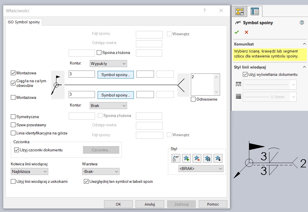
Substituting designation without model, that is, only in the documentation flat, You can use the command weld symbol immediately put annotations on the sheet. The program at this point uses the same interface as in the case of the 3D model.
Of course we also have drawings of two types of signs, ie. Caterpillar (caterpillar) and Finish (blackened triangle). These types are available from the menu by default annotations.
Then you can insert table joints also available on the Annotations tab > tables.
attention! If annotations joints were inserted in the picture (and not in the model), must select Include drawing annotations.
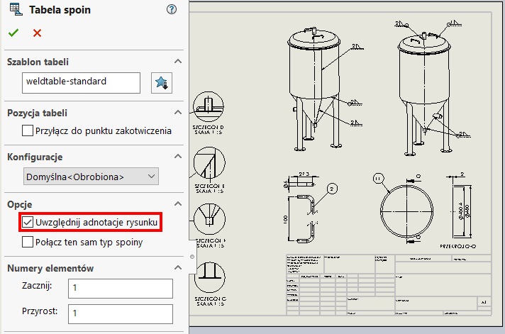
For example, the table looks like the picture below. Unfortunately, numbering welds to be carried out manually.
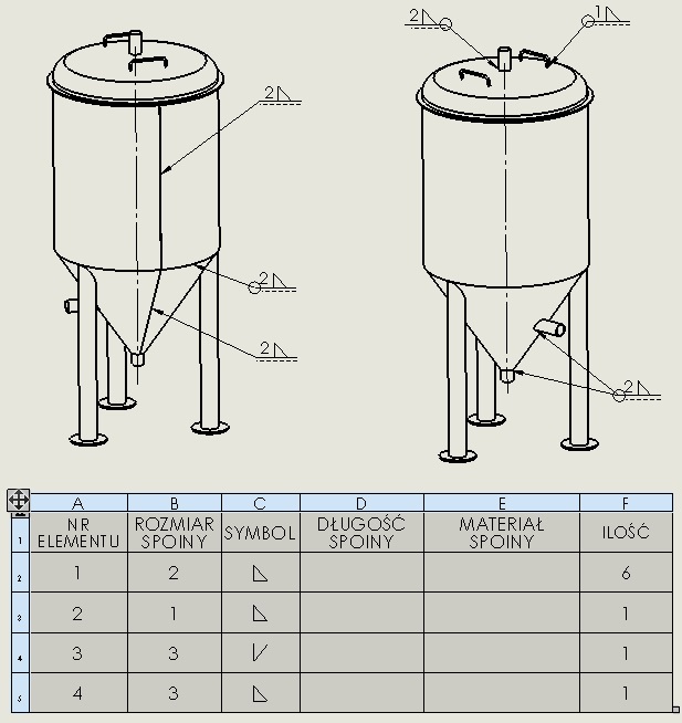
Is a better solution is to insert a table in the model at the design stage, or perhaps during the execution of documentation – ie drawing? Personally, I am a supporter of this second solution. However, sometimes show signs in three dimensions may help third parties understand the structure of the welding process.
More about adding joints in a 3D model can be found below.
