Do you know, that… ?
When modeling a surface may occur, that created the surface turns or otherwise deforms. Therefore apply guide curves. However, their use is not always necessary.
The aforementioned situation concerns Loft and boundary surface. Similarly, it can happen in solid modeling.
Example 1.
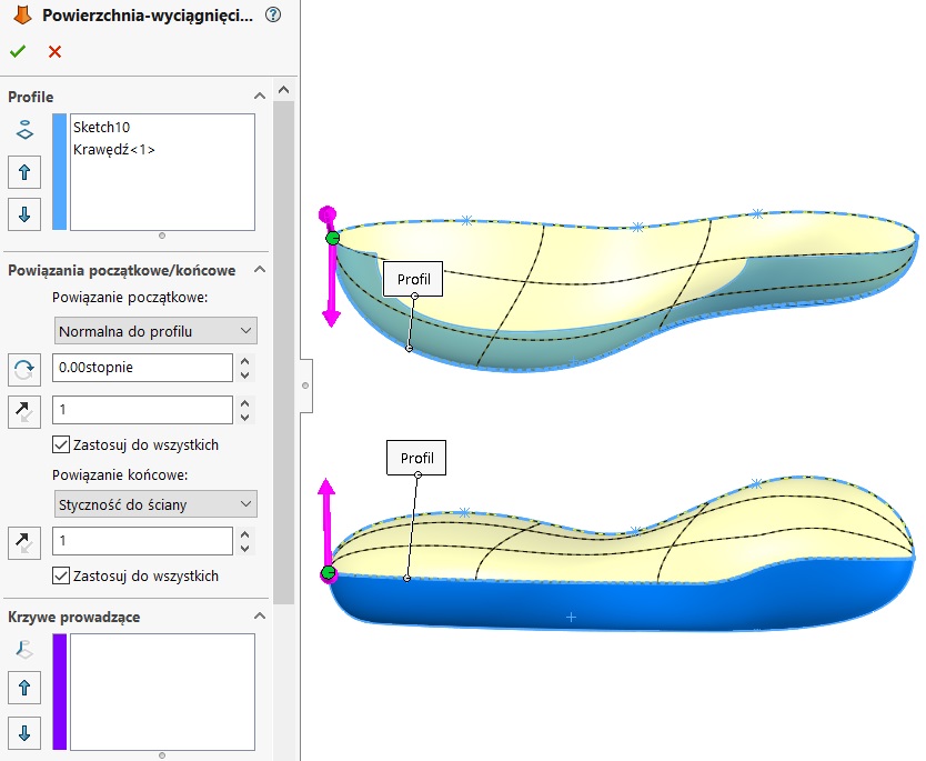
Lofted without the use of guide curves. One of the edges is much longer than the other. As a consequence, the surface of the torsion, exactly what you see when you turn on preview grid.
By right-clicking on one of the curves going Add connector. They should be set so that the grid lines intersect at right angles. Of course you can add multiple connectors, you can remove or reset position.
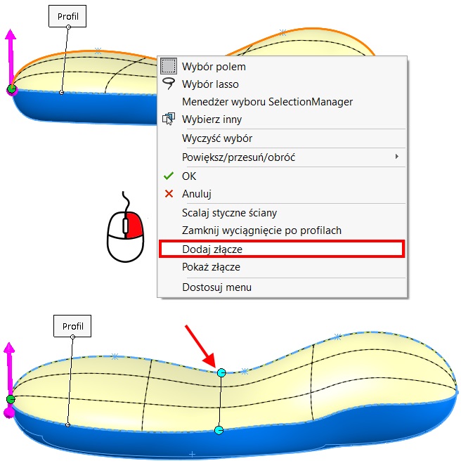
attention. If you are using guide curves, connector is not significant. No less they can also be used in addition to the guide curves.
Example 2.
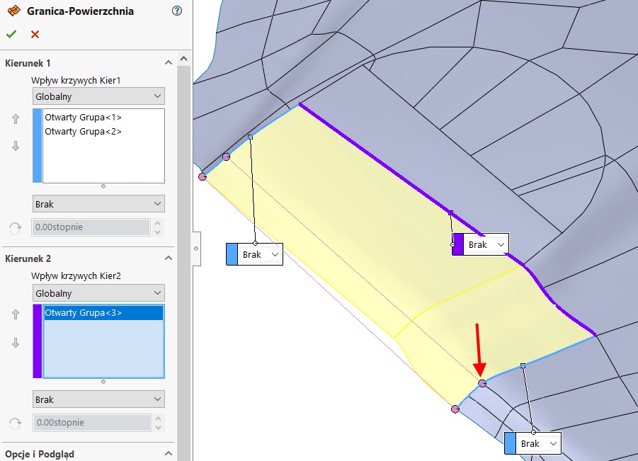
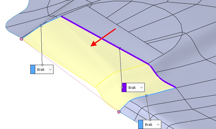
Add missing surface with a Boundary surface. Towards 1 on the one hand, point out a single edge, on the opposite side I have to choose three segments. In addition, the guiding curve pointed in the direction 2.
Also, now there was a twist of surface, due to this, the program combines the tops of the grid lines.
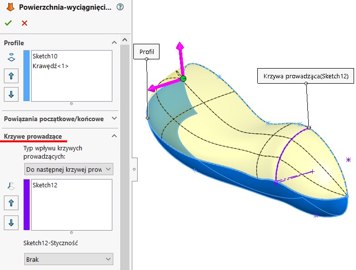
I choose Add connector.
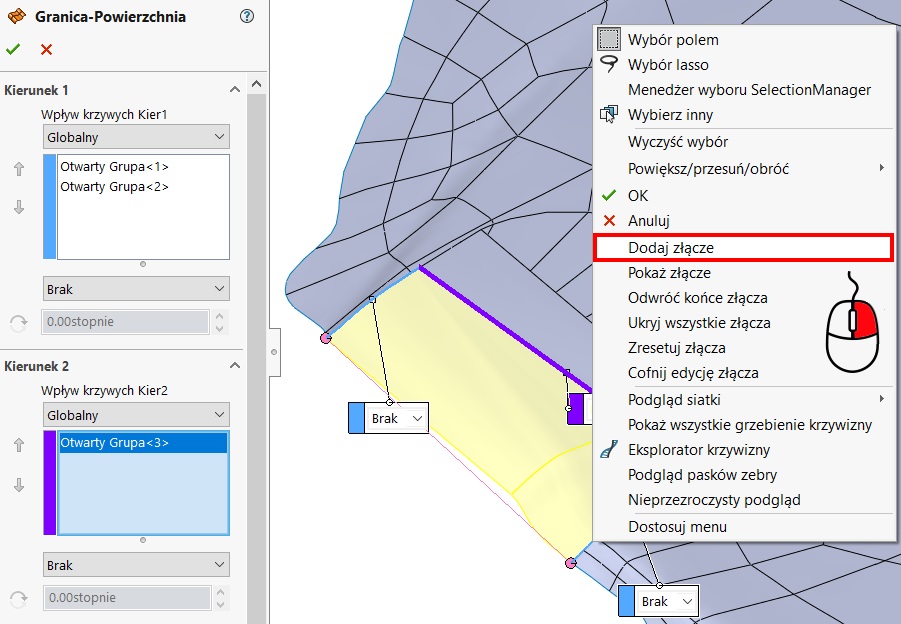
I set the position as shown below, to the grid lines were set as close as possible squareness. There is no need in this case insert the following connectors, layout grid lines sufficiently improved.