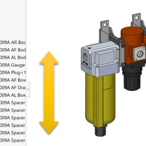
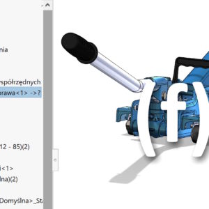
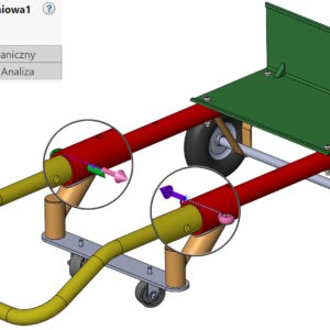
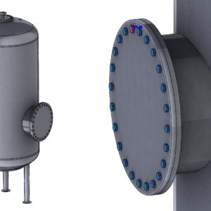
Component references are additional references that allow you to identify the same components in different places in the assembly. Dotoczy to zarówno części jak i podzłożeń. Pisałem o tym już kiedyś – link poniżej. Odniesienie komponentu i jego zastosowanie Dziś pokażę, w jaki sposób możesz zmieniać kolejność odniesień. Po pierwsze należy klikając na złożeniu pod prawym przyciskiem wybrać Edytuj odniesienia komponentów....
Category: <span>Assemblies</span>
Use the belt thickness in the Belt/Chain feature in the assembly
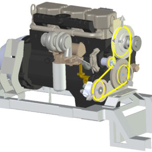
Belt/chain is an operation that allows the wheels to rotate using a virtual belt. Pasek ten jest domyślnie wyświetlony w formie szkicu – a więc nie zawiera geometrii 3D. Jednak możesz utworzyć część pasa, ale wcześniej ma sens włączenie opcji Użyj grubości pasa. Zwracam uwagę na bardzo istotny szczegół. Jeżeli koła są opasane wewnętrzną stroną pasa...
Cross out the missing item in the BOM table
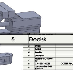
In the BOM table, both in assemblies and in drawings, you can choose to strike out the missing item in the material list option. It works this way, that the element removed from the assembly will be visible in the table with a strikethrough. Select the appropriate option when inserting the BOM table. Detailed options include:. numbering, whether it should be continued or replaced...
external references – filter by state
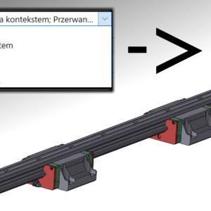
In contextual design, there are several statuses of external references. The most popular is, of course, the active tagged context – > po nazwie części. Jednak istnieją jeszcze inne symbole, including: przerwane odniesienie oznaczone “x”, zablokowane z oznaczeniem “*” lub poza kontekstem “?” . Przerwij odniesienie i zablokuj odniesienie w złożeniu Przeglądając odniesienia całego złożenia (po kliknięciu prawym...
Immobilization of all inserted parts for assembly
Everyone who works with SOLIDWORKS knows this fact, that the first component inserted into the assembly is fixed. Of course, this can be changed at a later stage of the project, but I'm writing about the default settings. Since two versions back, an option has appeared in the program that allows you to specify, what status does the inserted part take?. There are three options to choose from: Freeze only the first component Freeze Free ps....
Automatically repair incorrect mates in assemblies
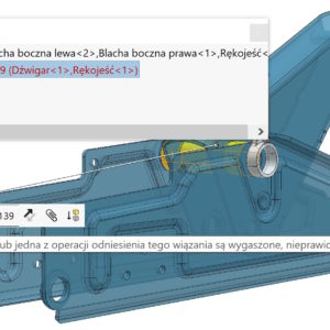
One of the basic activities in assemblies is repairing incorrect mates. Errors will appear after design changes or component swaps. Do you know, that there is an Xpert tool called Automatic Repair? At the time, when a binding error is displayed, indicated by a red arrow next to the file name, you can view the bindings with the wrong one and select Automatic Repair. The possibilities are....
Changing the direction of shooting then and now
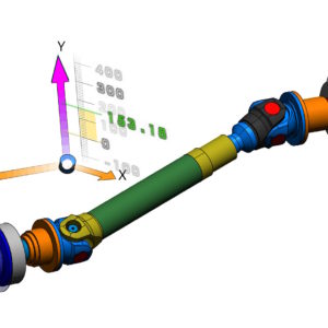
In assemblies, different components can have different orientations – it's natural. However, when we do the shooting, directions are related to the global 3D layout. In other words, clicking on the X arrow component,Y, Z will be set as indicated by the triad in the lower left corner of the screen. This may result in a collision when moving components. However, there is a solution! In order to...
Smart explode lines in exploded views
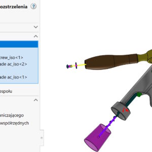
After you create an exploded view in assemblies, sometimes there is a need to show the shooting line. Starszy typ linii nazwany jako Szkic linii rozstrzelenia działa bardzo słabo, w mojej ocenie ma sens jedynie po zaznaczeniu ścian cylindrycznych. Z kolei nowsze rozwiązanie, czyli Inteligentne linie rozstrzelenia działają dużo lepiej, ale nie idealnie. Co mam na myśli? Otóż w rozstrzeleniu poniżej...
Use of a binding called Linear/Linear Connector
From the series, the less known Advanced binding, which serves to give linear motion to two components. Linear/Linear coupler works like this, that we point to a component 1 and linear direction, on which it moves and the component 2 and direction of movement. What is important, the direction can be anything linear (edge, axis, sketch line etc.) and it doesn't have to belong to this component....
Instances to replace in assembly arrays
Pattern in assemblies can refer to pattern in parts, but this solution is not always possible. In turn, the circular pattern in the SOLIDWORKS version 2023 gained new opportunities. These are the Instances to be replaced, which contain two tabs: Skipped Instances and Modified Instances. The first option already existed before, new is the ability to control omitted instances in configurations....

