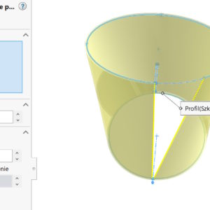
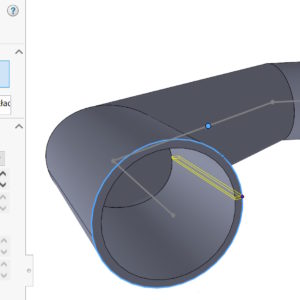
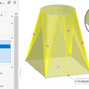
The bend drawn along the profiles provides great possibilities for forming sheets. There are two options in surgery, But I want to focus on the formed bend. The condition in this operation is the possibility of connecting two cut sketches with a straight line. There is one more condition in the case, When we want to display the bending line (Although formally such sheets are not bent). Well in both profiles ...
Category: <span>Sheet metal</span>
Ignore sloping walls when converting to sheet metal
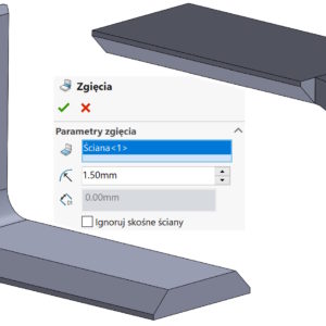
If you are converting objects with sheared faces on the bends to sheet metal, a problem may arise. Depending on the operation used – and there are two to choose from – the result will be different. And yes, for the Insert Bends command, if you check Ignore diagonal faces you will get the following result: And if you uncheck the above option you will get: However, in the case of the Convert... operation.
Option Show groove of the flat pattern of the sheet metal model
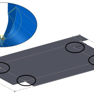
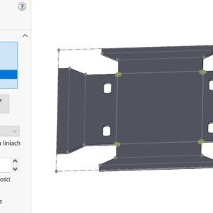
Making circular and rectangular corner cuts in sheet metal, depending on the parameters, a slight indentation may occur. Of course, this indentation is also visible on the unfolded model. Wanting to turn them off, you need to edit the Flat Model operation and uncheck the Show groove option.
Cutting in sheet metal with new possibilities
With SOLIDWORKS 2024 There are new possibilities of an operation called Slitting available on the Sheet Metal tab. The most classic method involves cutting a cylindrical sheet for further conversion into sheet metal. This is practiced many times, e.g. in the situation, when the base is a welded structure. But you can cut an element in many other cases, examples below. Unusual cut in the conversion...
You cannot turn off sheet metal flat mode?
If it happened to you, that the program prevents you from leaving the unfolded mode in sheet metal – check below, what can you do about it. Possibility number one is simply reconstruction (CTRL+B) or the so-called. forced reconstruction (CTRL+Q). Another option is to suppress the layout in the feature tree, because unfolding the sheet is nothing more than extinguishing the Unfolded Model operation. So...
Break in the corner, that is, the impact of the Refer to endpoint option
In lofted sheet metal sections as Bent between a circle and a rectangle, if you control the Number of bends, there may be a strange pause. It is a consequence of this, that the upper arc converges to one point at the bottom. Taking into account the thickness, radii and the number of bends, these walls simply do not fit there. However, there is an option to Refer to endpoint, default....
Defining default sheet metal parameters
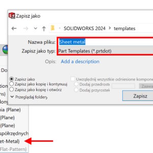
You create parts from sheet metal and each time you have to define bending parameters? It's not true. You can save the settings in a document template! To do it, draw a sketch and create a plate with the expected parameters: thickness, radius and allowance. Then delete this feature and the sketch, leaving the sheet metal folder. Now save the empty file as a part template. If next....
Corner undercut – if you don't have to, then do it in 2D
You can make undercuts in the corners of sheet metal sheets in two ways. you can tell, that everyone uses options, which suits him. However, there is one more aspect – performance! Today, using the example of a relatively simple sheet of metal, I compared two operations operating on a unfolded sheet and on a bent sheet. If you don't need to make the undercut visible in three dimensions – give it up! Of course...
Defining machining allowance in sheet metal
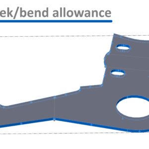
In sheet metal, depending on the cutting method (laser, wire, waterjet, e.t.c.) an appropriate allowance must be provided. Of course, it's not about the bending allowance (the so-called. coefficient k)m only additional material after the outline. How can you get this? Method 1. Move the walls away. Use the Move Wall operation to move walls away, after which it will be indented by the required....
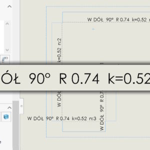
Customized display of sheet metal bending parameters
By default, when inserting a flat sheet metal drawing, lines and bending notes appear. However, you can influence this, what will be displayed above or below the bending line. However, I have a suggestion. If you simply add the missing parameters by clicking the appropriate icons – the drawing becomes illegible. Of course, you can add e.g. k=0.74 (k is the coefficient) e.t.c., but you need...

