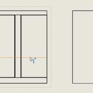
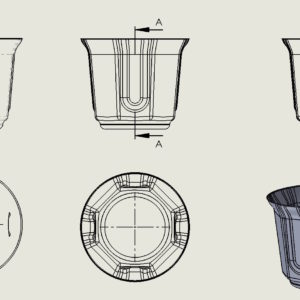
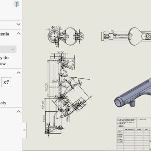
Everyone, whoever makes drawings in SOLIDWORKS has certain observations. Thin-walled elements or such will be particularly problematic, where there are lots of invisible edges. The problem appears when, for example:. dimensioning, because the program tries to attach a dimension to each edge. However, you can remedy this by turning off the options below – i.e. selecting in ULU and ULW modes. Additionally, you can increase....
Category: <span>Drawings</span>
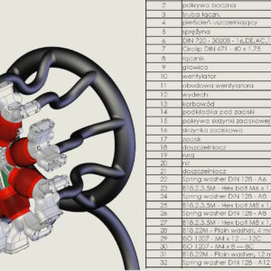
Show all configurations in BOM drawings
It is possible to show selected configurations in the BOM element list. Of course you can see, which components are present in a given configuration. However, the problem is this, that you can see the QUANTITY column, but it is not known which configuration it applies to… Therefore, a good solution is to enable Show all configurations under the right button after clicking in the row with the quantity. From now on, before the quantity described....
Hide outdated dimensions and annotations in drawings
Admit, that you happened to open a drawing, which was full of outdated dimensions? Outdated dimensions/annotations (also sketch relations in 3D models) They are olive green by default. Very good, that they are distinguished in a specific way, less good if you need to save the drawing, and it's full of outdated dimensions. There is a solution to this, just hide their visibility! Mark...
Toggle from the quick dimensioning keyboard
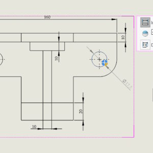
Quick dimensioning is a program functionality that automatically places a dimension on one side of the model. In the case of diameters, the program displays a manipulator that allows you to locate the dimension in one of the four quadrants of the system. You can also switch positions using the TAB key. Similarly, in the case of linear dimensions, you can switch the position using TAB.
Searching in the list of materials using filters
By pressing this magic button on the BOM list of materials, a search field will appear, or rather filtering. Of course it makes sense, if the lists are extensive with many items. You can search or filter each column. However, by selecting Custom Filter, you can define the criteria much more precisely, even forming conditions.
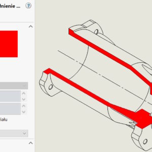
Changing the color of hatching in technical drawings
I present simple ways to change the color or hatching style in sections and half-views - half-sections. Both solutions require the inclusion of additional toolbars – Line Format or Layer. 1. format lines. Select the dashed area and on the Line Format tab, select Color. Remember to switch the color switching mode. 2. Layer. Layers in....
Component reference and its use
You can assign an identifier to an individual component instance in an assembly. To do this, edit the Component Properties and complete the Component Reference. E.g, you can use Component References to store reference designators for a printed circuit board assembly or an electrical wiring assembly. When different instances of the same component have different Component Reference values, these instances can be displayed as separate...
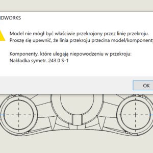
Why sometimes you can't make a cross-section correctly?
If you have encountered such an error: “The model could not be properly cut through the section line (…)” – then this post may help you understand it. The above-mentioned problem may appear in the drawing when making a cross-section. If it appears, this is definitely related to the zero thickness geometry error. This is a known situation, when e.g. you make a hole....
Show or hide tangent edges in a drawing
Settings in SOLIDWORKS can be divided into global and local ones. By global I mean the settings in the system options, that concern the entire program and not a specific document. These settings include displaying tangent edges. Such edges will be visible everywhere between adjacent walls. Long ago, when I studied technical drawing in college, on paper of course....
When is it worth taking dimensions from the model and when not?
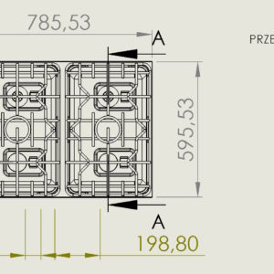
The ability to download dimensions from a model to a drawing is a very cool functionality. However, this doesn't always make sense. I will show two situations, when it is worth taking dimensions and when I advise against it. The first situation is this, when the model is geometrically complex and cannot be dimensioned in the drawing. Then I take the dimensions from the model and anyway, that they are not....

