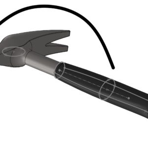
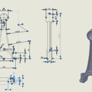
Today I will present 3 ways to copy and move geometry in a SOLIDWORKS sketch (which most users do not know). Working with sketches is the foundation of modeling in SOLIDWORKS. Yet many users only use basic methods for copying and moving sketch entities. Meanwhile, the program offers several quick and very convenient ways, that can save a lot of time - especially when....
Author: Paul (Paul Kęska)
format lines – the most useful bar in drawings
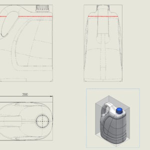
The most useful toolbar, which I also turn on in drawings is Line Format. This small toolbar contains very useful tools, allowing you to change the color of lines or edges, thickness and its style. Additionally, you can manage layers from there. I have already written about the applications many times, in this example, it was used to highlight the level of liquid in the designed bottle. Other uses? Very...
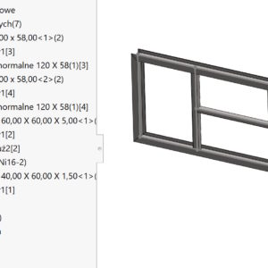
Saving an assembly from a weldment – why it was done this way?
How can you update the position of a part in an assembly, which were derived from the welded structure?
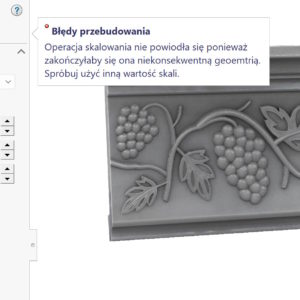
Stretch the imported item
Each element can be stretched using selected operations. They are especially useful for imported files.
Automatically arrange components – influence of the bounding box
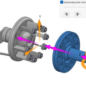
When exploding, you can automatically arrange components using the so-called. chain. Auto-Explode – why is this not in SOLIDWORKS? Please remember this option, that the order in which parts/subassemblies are selected will affect the moving order. The second important issue is setting alignment using a bounding box, where you can choose: center of the bounding box, front edge of the frame, the rear edge of the frame. Frame...
Options for displaying dimensions in a sketch
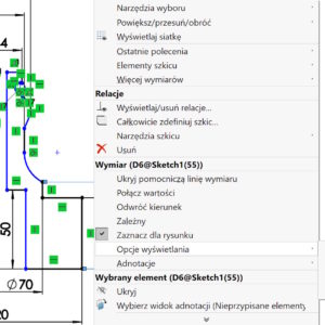
In most cases, we focus on correctly displaying dimensions in drawings. And it makes sense, of course. But in 3D models you can also use several options available by clicking the right button > Display options. What is important, are not available during dimensioning, only after turning off the tool (only the arrow is visible). Among other things, there are options for Centering the dimension or....
Mass properties – show weld bead weight
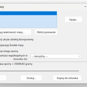
In some structures, e.g. tanks, hulls, cranes, heavy machinery, joint mass can reach 3–8%. This is so much, that this is not a negligible quantity. This is especially important in the offshore industry due to buoyancy and stability. From the designer's point of view, it is crucial to calculate the weight of the joints. ATTENTION! The weight of welds can be calculated in the case of a bead..
e-book in a Christmas gift box version!
Another Christmas is fast approaching. On this occasion, I have a gift idea for you. The latest SOLIDWORKS e-book 2025 in a Christmas box edition on CD. Let me remind you, that e-book containing 760 exercise pages (from beginner to advanced) is a publication intended for self-study of SOLIDWORKS. It covers areas such as: basics of modeling, deposit,...
Where the imported file is saved is important
Working with imports comes naturally to most of us. I have written about various aspects related to this many times. The examples below. Inserting an imported file into a SOLIDWORKS part Direct editing in imported files 3D Interconnect with new opening options Today I will pay attention to where the file is saved. Well, when we download import files, we often save them....
Select all dimensions or axes
In SOLIDWORKS, the CTRL+A key combination means “select all”. For example, selecting a face in the 3D model and selecting CTRL+A will select all faces. How to convert a surface into a solid and vice versa in one operation? This command also works in drawings. And yes, if you select one dimension and then CTRL+A – the program will select all dimensions. It will behave similarly....

