Do you know, that… ?
The three-dimensional design of welded structures can be used a number of techniques. You do not always have to pull out all the structural members on the draft, you can often take advantage of the mirror array or object.
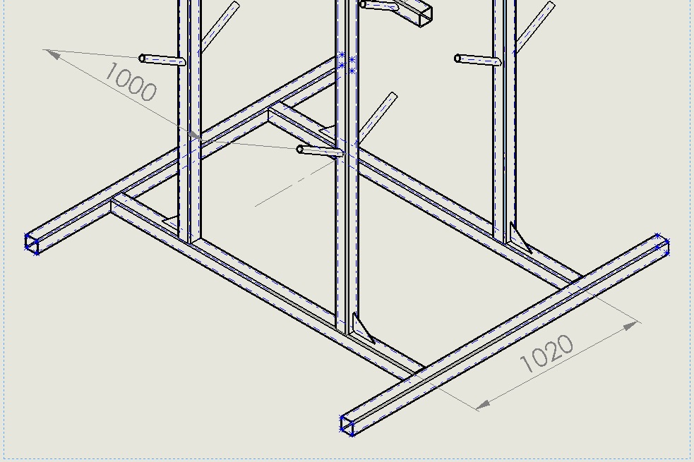
In this case, the geometrical center line of the sketch has no.
This in turn may make it difficult to show dimensions on drawings. See how you can quite quickly insert axes in profiles other than circular pipes.
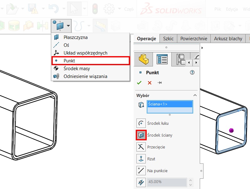
1. interposition geometric point the middle wall.
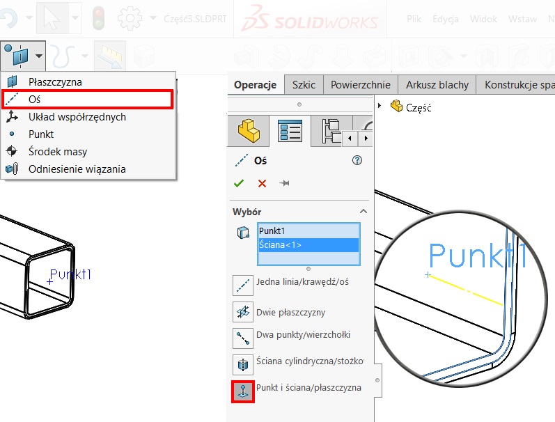
2. interposition axis indicating point and the wall. If the ends are cut members, you can put the plane in relation to the axis of the walls and their intersection.
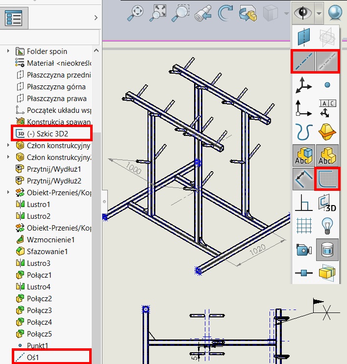
The figure is sufficient to show: sketches, axles and axles temporary. remember, that the pipes do not need to insert the round axis (where there is no draft in the middle), as the program automatically generates the so-called. temporary axes. On the other hand drawings of the framework must be seen in the drawing. But you can show them in the tree, regardless of, whether they have been hidden in the model window.
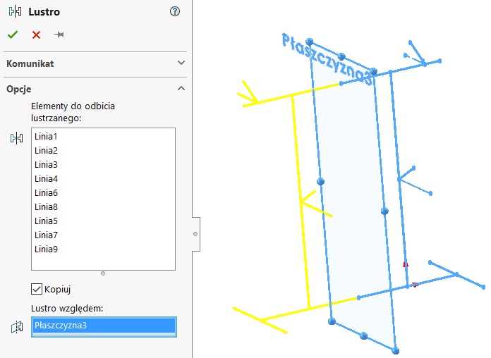
There is such a possibility, that after finishing doing modeling copy of the entire skeleton sketch by converting to a 3D sketch. Then bounce this sketch relative to the plane mirror. In this manner sketches in the middle of each tube, unfortunately, you can do so only in the case of symmetrical design.
Leave a Reply