Some processes in SolidWorks require significant RAM resources. For example, when calculating SolidWorks Simulation Solver Direct Spars, it requires 1 GB na każde 200 000 stopni swobody (DOF). What to do, kiedy fizycznie mamy zbyt mało RAMu? Możesz zdefiniować tzw. pamięć wirtualną. W tym celu należy wybrać Zaawansowane ustawienia systemu. Następnie wybieramy zakładkę Zaawansowane > Pamięć...
Category: <span>All</span>
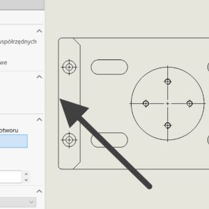
DimXpert – automatic dimensioning from the center of the edge
In DimXpert, you can dimension drawings based on the vertex or center of the hole/cylinder. But what about the situation?, when we want to dimension symmetrically, and you cannot indicate the center of the edge? Of course, you can divide the wall with a division line, but this is the so-called method. invasive, resulting in a change of wall IDs. Hence, existing dimensions will be out of date and if the wall...
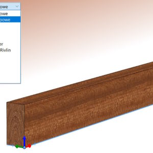
Defining an orthotropic material in SOLIDWORKS
Can be assumed, that all default materials in the SOLIDWORKS material database are isotropic. Is it possible to define an orthotropic material?, that is, representing different physical properties in different directions? An example of such a material is wood, whose properties differ significantly in the longitudinal and transverse directions. Well, such properties can be described. However, the condition is that the Simulation i add-in must be launched first..
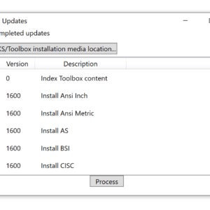
One of the methods of updating the Toolbox database
Toolbox is a database of standardized elements and, like other SOLIDWORKS files, is subject to updates. Similarly, the program does not read files from newer versions, and the older ones should be saved in the current one. About that, The following message indicates that the database is incorrect: One update method is to run an application located in the installation directory called sldtoolboxupdater....
Additional useful options in the Move/Copy operation
The Move/Copy operation is widely used in modeling multibody parts. The rotation and carrying handle was changed some time ago. In SOLIDWORKS version 2023 further changes appeared. Otóż wielkości liczbowe definiujące obrót lub przeniesienie stały się parametryczne! W związku z tym można je konfigurować lub sterować nimi za pomocą równań. W zakładce Obróć dodano możliwość...
Analytical calculations vs. FEM calculations on the example of a beam
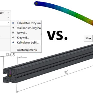
As is known, the FEM finite element method in calculations, is always subject to the risk of error. It results from many factors, from the given restraint and load, ending with an inappropriate mesh or incorrect interpretation of the results. Today I will try to compare two methods based on available SOLIDWORKS tools. The material used for calculations is Aisi Steel 304 z Re=206 MPa. Beam length....
Is it possible to save a file from SOLIDWORKS in a neutral format with appearances?
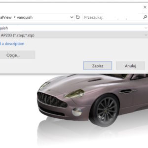
Neutral format (sometimes called open) are mainly STEP and IGES files, sometimes Parasolid. Such files are mainly used to transfer 3D geometry. But in the file you can save, among others:. appearances (texture). Świetnie w przypadku SOLIDWORKS sprawdza się format parasolid (for SW native), which allows the transfer of appearances both in parts and assembly. In the case of STEP (both0 203...
Improve accuracy for surfaces contacting without penetration
When conducting a simulation, it is very important to choose the right options. It is, that the restraint conditions have the greatest impact on the results. However, there are many more components. Lately, During some calculations, I tried to compare the exact contact options. You can do this option (and in fact you should) enable in the study properties. W zakładce Opcje należy zaznaczyć Popraw dokładność...
Why do parts in an assembly open with feathers and what does it affect??
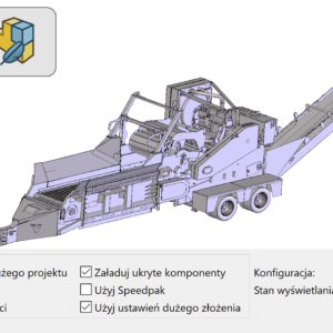
A blue feather next to the part in the assembly tree indicates this, that it was loaded in Lightweight mode. This is a special mode, which allows you to open assemblies faster by keeping file information to a minimum. Of course, if we want to edit the file or make a cross-section, we must load it to full memory. Loading an assembly with lightened components is faster than loading....
Show or hide tangent edges in a drawing
Settings in SOLIDWORKS can be divided into global and local ones. By global I mean the settings in the system options, that concern the entire program and not a specific document. These settings include displaying tangent edges. Such edges will be visible everywhere between adjacent walls. Long ago, when I studied technical drawing in college, on paper of course....

