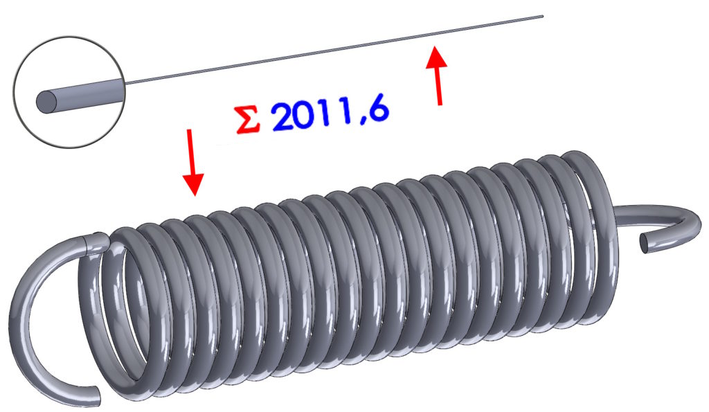
This topic appears in many places and is not described clearly enough. So today I'll zoom in, how to create a configuration, which shows the expansion of the spring. Of course, it can be any shape drawn along a path.
1. The path must be one continuous curve. Even if you use e.g. composite curve, ultimately it has to be hers fitted 3D spline, because only he can be dimensioned. Unfortunately, it is not possible to dimension the sketch in editing, because it is defined (black).
2. Therefore, in the second step, you need to add the dimension of the curve length (spline) as the so-called. reference dimension. We simply add a dimension to the gray sketch, which must be made visible in advance. This dimension will be marked as RD@.
3. Now I insert a circle sketch on the end face (or I use the profile used in the extrusion) and I extend it to a distance equal to the length of the spline. For this purpose it is best to create equation, i.e. in place of the value, I enter the = sign and click on the visible RD dimension in the graphics window. attention! It should be deselect merging results, to create a disjoint solid object.
4. In the fourth step, I create additional configuration, naming them as you wish. In one configuration, I leave the sweep restored, and additional operations suppressed, and in the second one I delete the object (rolled up) and I leave the one I just pulled out.
If you don't need to create a configuration, a jedynie pobrać długość rozwinięcia – po prostu wczytaj wymiar długości jako właściwość dostosowaną.

