Do you know, że… ?
In welded structures, similar to assemblies, when creating technical documentation, we insert tables. In many cases, the order in these tables is important.
In today's post I will focus on the so-called. Cut leaves of welded structures.
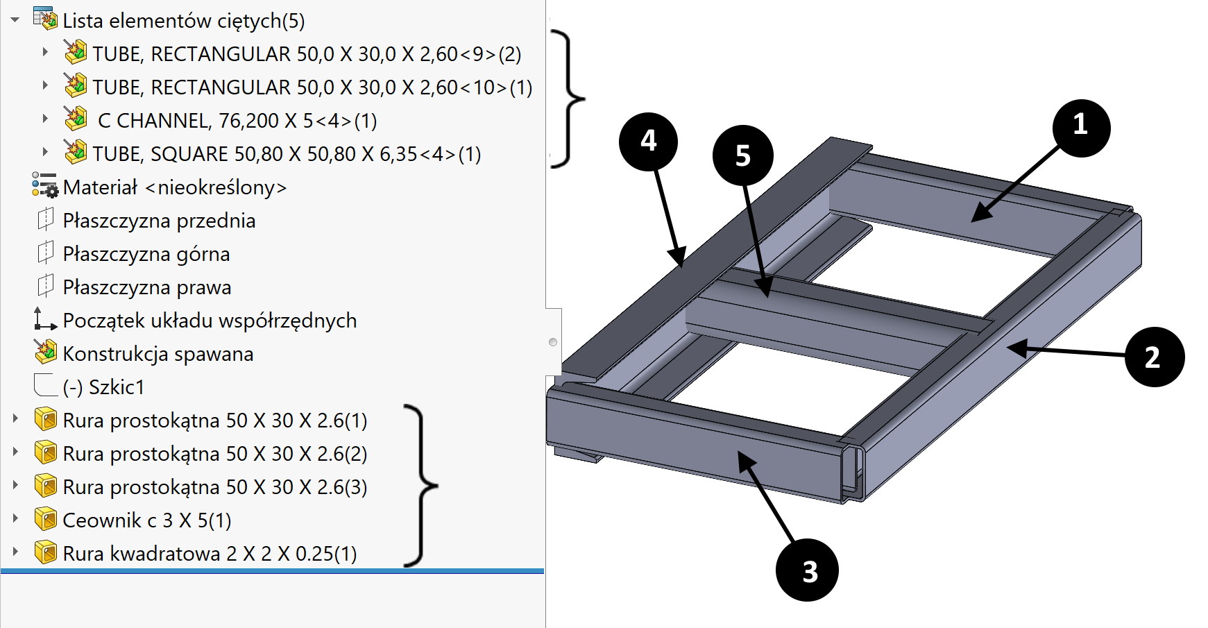
In general, the order in the table depends on the order in which the structural members are created. In this case, I created the members from 1 do 5 and this sequence is shown in the table. Being items 1 i 3 are identical objects, so under the heading 1 there are two instances.

Ale nie zawsze tak będzie…
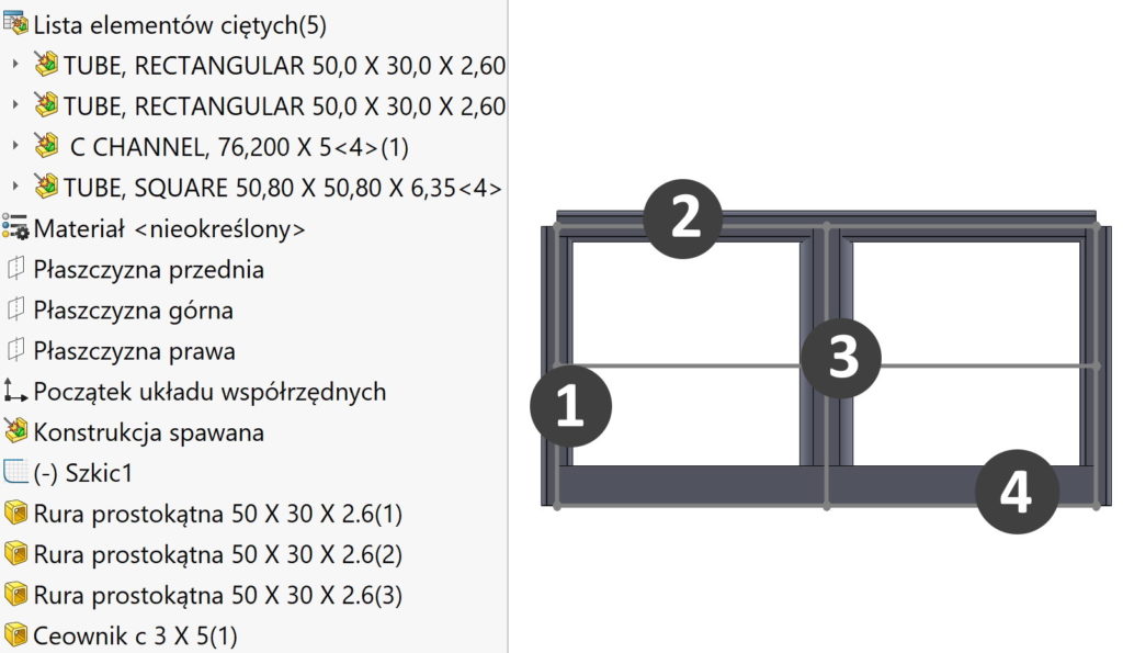
If I move the scroll bar above the first segment and add a new segment there, in the cut-list it will be at the end. Despite this, that this is the first operation in the tree.
So how do we control the order in the list, and hence in the drawings?
1. You can move features in the tree or move folders in the cut list. remember, that the reordering of the feature tree depends on the interrelationship and in many cases will not be possible.
2. The second option is to change the order in the cut list properties window. Only after confirming with OK, the view in the tree of operations will be refreshed.
3. Trzecia możliwość to podobnie jak w BOM – zmiana kolejności w tabeli listy elementów ciętych. Kolejność zmienia się przeciągając dany wiersz góra – dół.
And finally, one important piece of information.
By changing the order in the list of cut elements, you cannot see this change in the drawing in the inserted table! Why? This is because, that welded structures default to two configurations (machined and welded). I jeżeli dokonujesz zmian kolejności przez przeciągnięcie w liście elementów ciętych – prawdopodobnie odbywa się to w konfiguracji processed (active by default)!
In contrast, in the figure, the table only refers to a welded configuration, in which as seen above, the order has not changed at all. All this should be considered when doing this type of order modification.

