Do you know, że… ?
Dimensioning angles in SOLIDWORKS does not always meet constructors' expectations. In particular, it is about profiles (e.g. in welded structures), that connect obliquely.
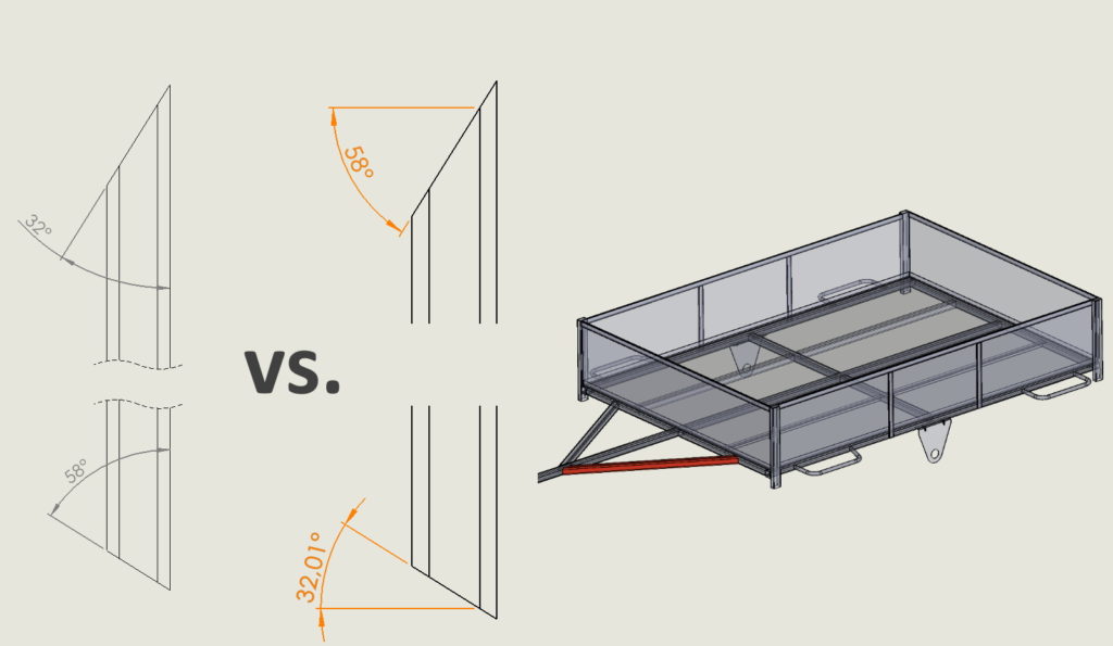
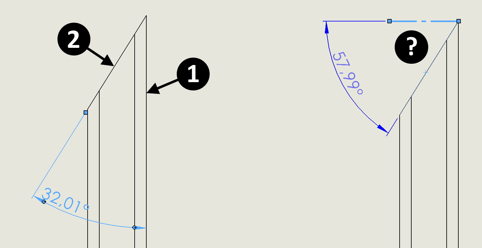
When dimensioning such objects in drawings, you can insert an angular dimension between two edges (1) and (2). Depending on its placement, it will be either acute or obtuse. However, this is not the so-called. angle on the saw, który jest mierzony pomiędzy krawędzią ściętą a linią prostopadłą do osi – rys. on the right.

What can you do?
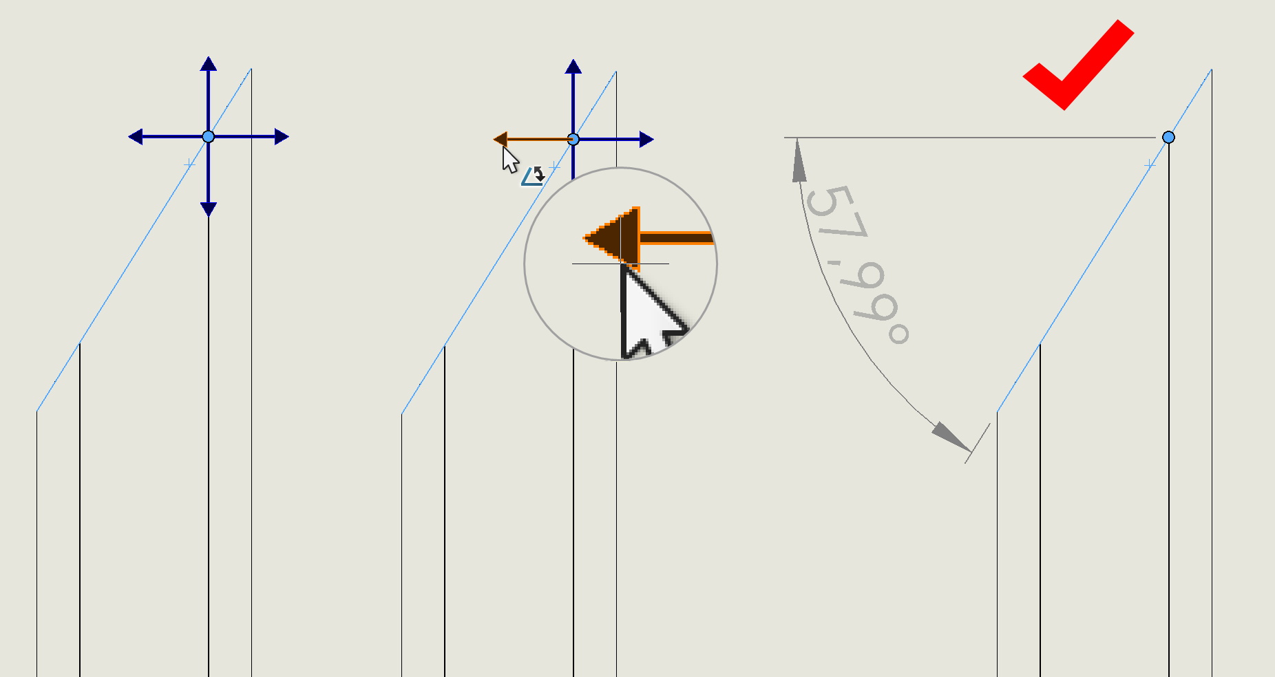
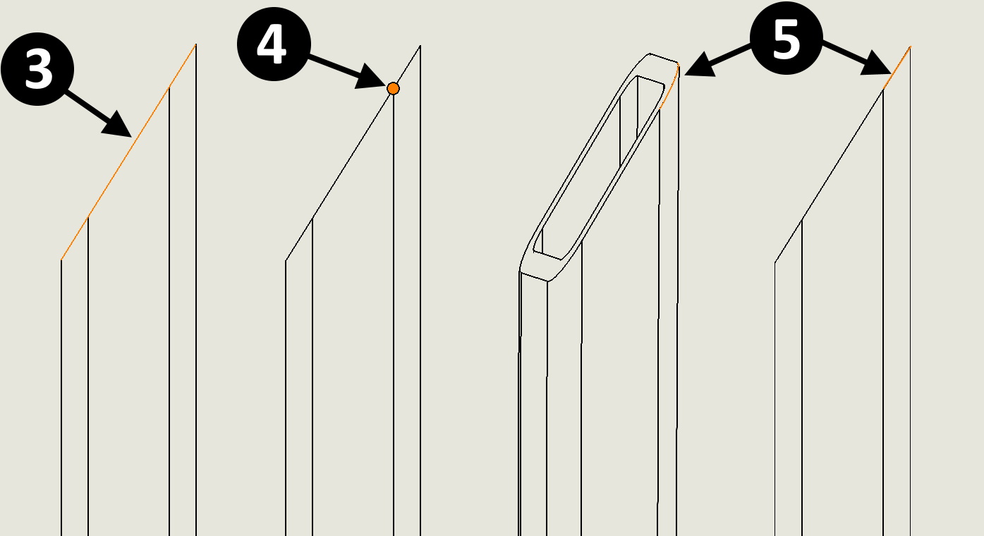
Well, you can insert a datum and dimension the angle between its axis and the edge. To insert such a layout, select the edge in sequence (3) and point (4). Ten punkt tak naprawdę powinien być na końcu – w narożniku, but unfortunately this cannot be done in this case. This is because, that edge (5) it is not linear and cannot be selected instead (3). If the metallurgical profile did not have rounding, albo po prostu będziesz wymiarował inny detal – wskaż wierzchołek w narożniku!

After selecting the edge and vertex, a four-axis layout appears. Now create an angular dimension between the layout axis and the cut edge. And there is success! The only inconvenience is the fact, that the dimension is not taken from the vertex, but as I wrote, this cannot be done in such a profile.