Do you know, że… ?
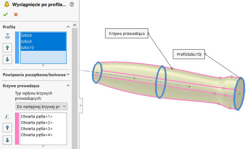
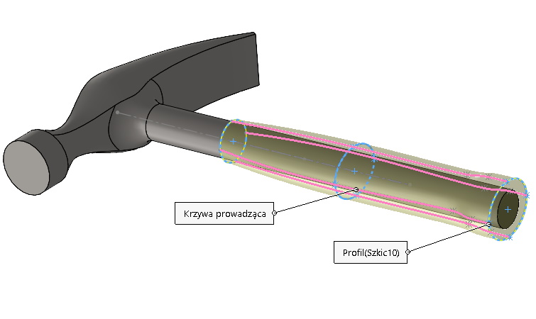
View, how to correctly define Lofted.
This operation creates an extrude between the profiles, which can be sketches, edges of solids / surfaces or faces. Additionally, you can define guide curves, however, they are not required. In the operation itself, you can set the so-called. start and end constraints and different types of curve influence.

If you want to extrude geometry between two profiles (for illustration let's assume, that they are circles), it is not enough to mark these sketches in the box Profile. In that case, we are not sure, that there is a perfect circle at every point of the cross section. In principle, it can be assumed, that it won't be a circle!
This is because, that there is an involuntary twisting of the virtual connector between the profiles. Manually setting it cannot be done perfectly.
In a more complex case, a possible twist may have a greater effect on the resulting geometry.
What solution can be used in this case?
- Solution number one is to draw the guide curves. In fact, one curve is enough, to align the grid, however, for symmetrical shapes, the curves should be symmetrical.
2. Solution number two is splitting the profiles. If the profiles are sketches, then you can do it by right clicking on the sketch > Sketch tools > Share items. For walls, a split line is used.
but remember, that the division must be made in each of the sketches in the same place. The second thing, a circle or e.g.. we divide the ellipse into two segments at least. It means, that it is impossible to put a single split point!

